2003 AUDI A8 lock
[x] Cancel search: lockPage 3 of 96
Downloaded from www.Manualslib.com manuals search engine 3
Attention
NoteNew
Contents
Page
Introduction . . . . . . . . . . . . . . . . . . . . . . . . . . . . . . . . . . . . . . . . . . 4
Body . . . . . . . . . . . . . . . . . . . . . . . . . . . . . . . . . . . . . . . . . . . . . . . . 6
Passenger Protection
System layout . . . . . . . . . . . . . . . . . . . . . . . . . . . . . . . . . . . . . . . . . . . . . . . . 14
Block diagram . . . . . . . . . . . . . . . . . . . . . . . . . . . . . . . . . . . . . . . . . . . . . . . . 16
Safety systems . . . . . . . . . . . . . . . . . . . . . . . . . . . . . . . . . . . . . . . . . . . . . . . 18
Engine, Mechanics
Technical data of V8 4.2 l 5V engine . . . . . . . . . . . . . . . . . . . . . . . . . . . . . . 24
Technical data of V8 3.7 l 5V engine . . . . . . . . . . . . . . . . . . . . . . . . . . . . . . 25
System layout . . . . . . . . . . . . . . . . . . . . . . . . . . . . . . . . . . . . . . . . . . . . . . . . 30
Electrohydraulic torque reaction support . . . . . . . . . . . . . . . . . . . . . . . . . 32
Exhaust system . . . . . . . . . . . . . . . . . . . . . . . . . . . . . . . . . . . . . . . . . . . . . . . 33
Fuel tank . . . . . . . . . . . . . . . . . . . . . . . . . . . . . . . . . . . . . . . . . . . . . . . . . . . . 34
Automatically controlled starting . . . . . . . . . . . . . . . . . . . . . . . . . . . . . . . . 41
Gearbox . . . . . . . . . . . . . . . . . . . . . . . . . . . . . . . . . . . . . . . . . . . . 45
Running Gear
Front axle . . . . . . . . . . . . . . . . . . . . . . . . . . . . . . . . . . . . . . . . . . . . . . . . . . . 49
Rear axle . . . . . . . . . . . . . . . . . . . . . . . . . . . . . . . . . . . . . . . . . . . . . . . . . . . . 50
4-level air suspension . . . . . . . . . . . . . . . . . . . . . . . . . . . . . . . . . . . . . . . . . 51
System layout . . . . . . . . . . . . . . . . . . . . . . . . . . . . . . . . . . . . . . . . . . . . . . . . 52
Electric parking brake . . . . . . . . . . . . . . . . . . . . . . . . . . . . . . . . . . . . . . . . . 53
Adaptive cruise control . . . . . . . . . . . . . . . . . . . . . . . . . . . . . . . . . . . . . . . . 54
Electrical System
Bus topology . . . . . . . . . . . . . . . . . . . . . . . . . . . . . . . . . . . . . . . . . . . . . . . . . 58
Convenience and security electronics . . . . . . . . . . . . . . . . . . . . . . . . . . . . 64
Lighting system . . . . . . . . . . . . . . . . . . . . . . . . . . . . . . . . . . . . . . . . . . . . . . 68
Heating/Air Conditioner
Design and operation. . . . . . . . . . . . . . . . . . . . . . . . . . . . . . . . . . . . . . . . . . 72
Operating principle . . . . . . . . . . . . . . . . . . . . . . . . . . . . . . . . . . . . . . . . . . . 74
Blower unit/air routing . . . . . . . . . . . . . . . . . . . . . . . . . . . . . . . . . . . . . . . . . 76
System layout . . . . . . . . . . . . . . . . . . . . . . . . . . . . . . . . . . . . . . . . . . . . . . . . 80
Block diagram for front air conditioner . . . . . . . . . . . . . . . . . . . . . . . . . . . 86
Block diagram for rear air conditioner . . . . . . . . . . . . . . . . . . . . . . . . . . . . 88
The Self Study Programme contains information on design
features and functions.
The Self Study Programme is not intended as a Workshop
Manual. Values given are only intended to help explain the
subject matter and relate to the software version applicable at
the time of SSP compilation.
Use should always be made of the latest technical publications
when performing maintenance and repair work.
Page 10 of 96
Downloaded from www.Manualslib.com manuals search engine 10
Body
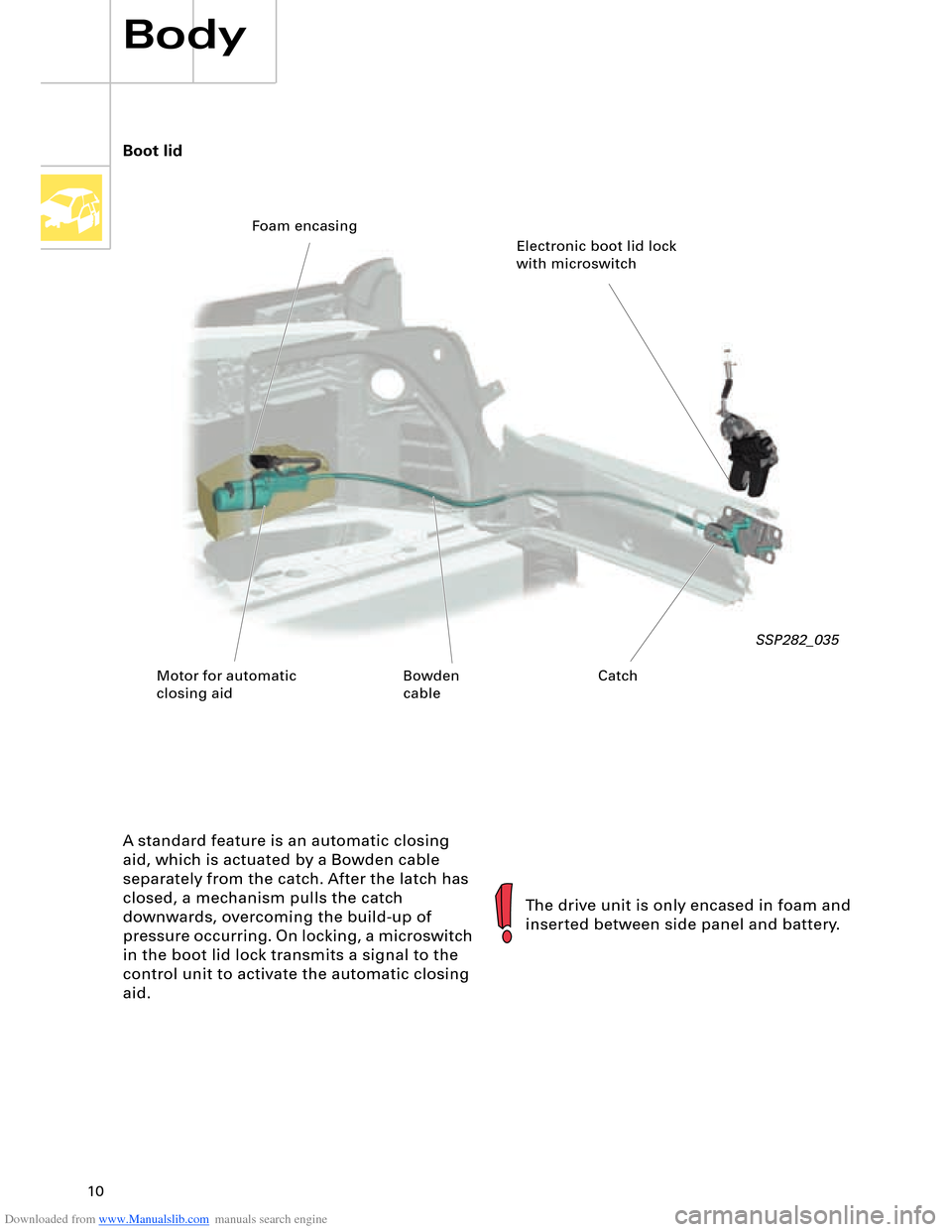
A standard feature is an automatic closing
aid, which is actuated by a Bowden cable
separately from the catch. After the latch has
closed, a mechanism pulls the catch
downwards, overcoming the build-up of
pressure occurring. On locking, a microswitch
in the boot lid lock transmits a signal to the
control unit to activate the automatic closing
aid.
SSP282_035
The drive unit is only encased in foam and
inserted between side panel and battery. Boot lid
Electronic boot lid lock
with microswitch Foam encasing
Motor for automatic
closing aidCatch Bowden
cable
Page 12 of 96
Downloaded from www.Manualslib.com manuals search engine 12
Body
Front doors
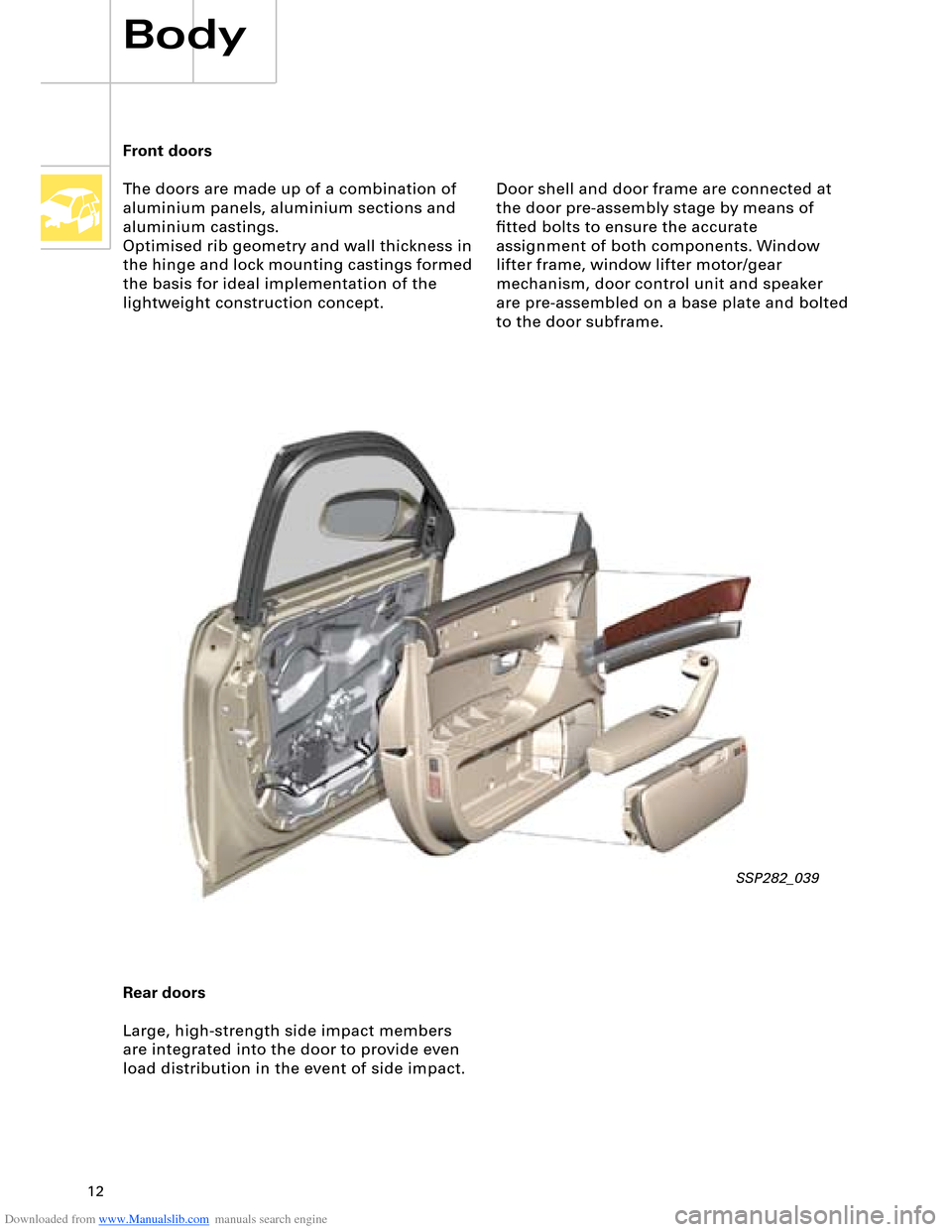
The doors are made up of a combination of
aluminium panels, aluminium sections and
aluminium castings.
Optimised rib geometry and wall thickness in
the hinge and lock mounting castings formed
the basis for ideal implementation of the
lightweight construction concept.
Rear doors
Large, high-strength side impact members
are integrated into the door to provide even
load distribution in the event of side impact.
SSP282_039
Door shell and door frame are connected at
the door pre-assembly stage by means of
fitted bolts to ensure the accurate
assignment of both components. Window
lifter frame, window lifter motor/gear
mechanism, door control unit and speaker
are pre-assembled on a base plate and bolted
to the door subframe.
Page 16 of 96
Downloaded from www.Manualslib.com manuals search engine 16
15
J234
J655
1
2
E224
3
G283G284G179
N131
F138
N202N199N200N201N95
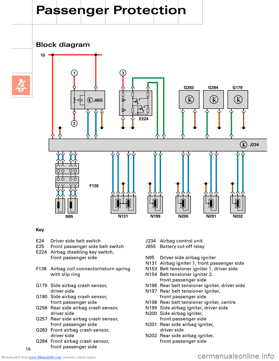
Key
E24 Driver side belt switch
E25 Front passenger side belt switch
E224 Airbag disabling key switch,
front passenger side
F138 Airbag coil connector/return spring
with slip ring
G179 Side airbag crash sensor,
driver side
G180 Side airbag crash sensor,
front passenger side
G256 Rear side airbag crash sensor,
driver side
G257 Rear side airbag crash sensor,
front passenger side
G283 Front airbag crash sensor,
driver side
G284 Front airbag crash sensor,
front passenger side
Block diagram
Passenger Protection
J234 Airbag control unit
J655 Battery cut-off relay
N95 Driver side airbag igniter
N131 Airbag igniter 1, front passenger side
N153 Belt tensioner igniter 1, driver side
N154 Belt tensioner igniter 2,
front passenger side
N196 Rear belt tensioner igniter, driver side
N197 Rear belt tensioner igniter,
front passenger side
N198 Rear belt tensioner igniter, centre
N199 Side airbag igniter, driver side
N200 Side airbag igniter,
front passenger side
N201 Rear side airbag igniter,
driver side
N202 Rear side airbag igniter,
front passenger side
Page 22 of 96
Downloaded from www.Manualslib.com manuals search engine 22
Passenger Protection
15 30
+
-
31
J644
J655
43
B
1
2
A
TerminalPinInput/outputDescription
30, battery A Input
(screw connection)U
bat. term. 30/battery
87 B Output
(screw connection)Output
Terminal 15 1 Input
(plug connection)Positive power supply,
interruptible
Vehicle earth 2 Input
(plug connection)Earth from
airbag control unit J234
Crash signal 3 Input
(plug connection)Crash signal from
airbag control unit J234
Diagnosis 4 Input
(plug connection)Diagnostic wire from
airbag control unit J234
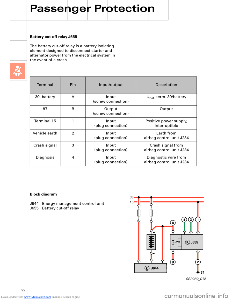
Battery cut-off relay J655
The battery cut-off relay is a battery isolating
element designed to disconnect starter and
alternator power from the electrical system in
the event of a crash.
Block diagram
J644 Energy management control unit
J655 Battery cut-off relay
SSP282_076
Page 32 of 96
Downloaded from www.Manualslib.com manuals search engine 32
Electrohydraulic
torque reaction support
Engine, Mechanics
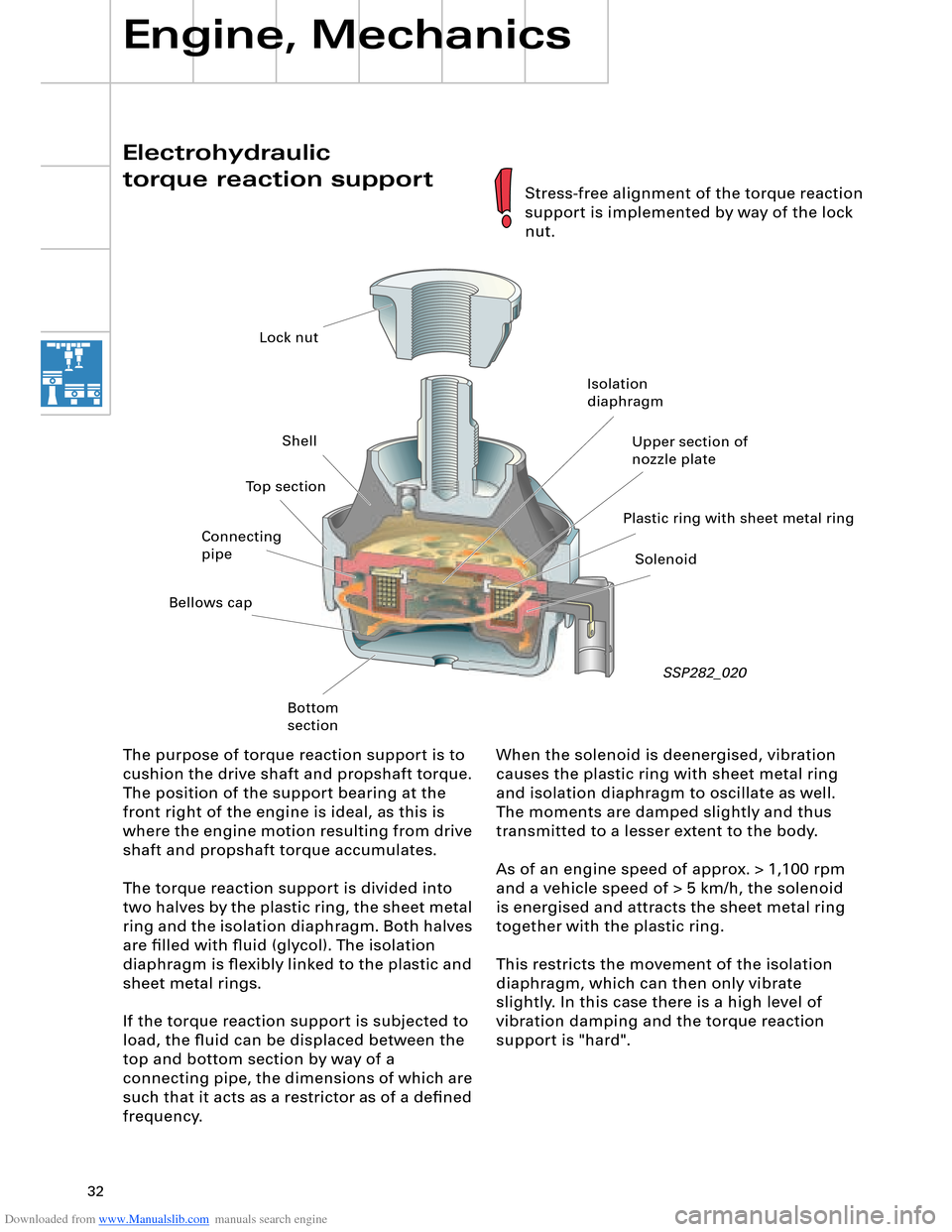
When the solenoid is deenergised, vibration
causes the plastic ring with sheet metal ring
and isolation diaphragm to oscillate as well.
The moments are damped slightly and thus
transmitted to a lesser extent to the body.
As of an engine speed of approx. > 1,100 rpm
and a vehicle speed of > 5 km/h, the solenoid
is energised and attracts the sheet metal ring
together with the plastic ring.
This restricts the movement of the isolation
diaphragm, which can then only vibrate
slightly. In this case there is a high level of
vibration damping and the torque reaction
support is "hard". The purpose of torque reaction support is to
cushion the drive shaft and propshaft torque.
The position of the support bearing at the
front right of the engine is ideal, as this is
where the engine motion resulting from drive
shaft and propshaft torque accumulates.
The torque reaction support is divided into
two halves by the plastic ring, the sheet metal
ring and the isolation diaphragm. Both halves
are filled with fluid (glycol). The isolation
diaphragm is flexibly linked to the plastic and
sheet metal rings.
If the torque reaction support is subjected to
load, the fluid can be displaced between the
top and bottom section by way of a
connecting pipe, the dimensions of which are
such that it acts as a restrictor as of a defined
frequency.
SSP282_020
Stress-free alignment of the torque reaction
support is implemented by way of the lock
nut.
Lock nut
Shell
Bellows cap
Bottom
sectionIsolation
diaphragm
Plastic ring with sheet metal ringUpper section of
nozzle plate
Solenoid Connecting
pipeTop section
Page 43 of 96
Downloaded from www.Manualslib.com manuals search engine 43
D1
30
15
J329J53J695J694
75xE415
N376
6x
J623
J518
50R
50R
3
12
12
E408
STOP START
58s
210 210
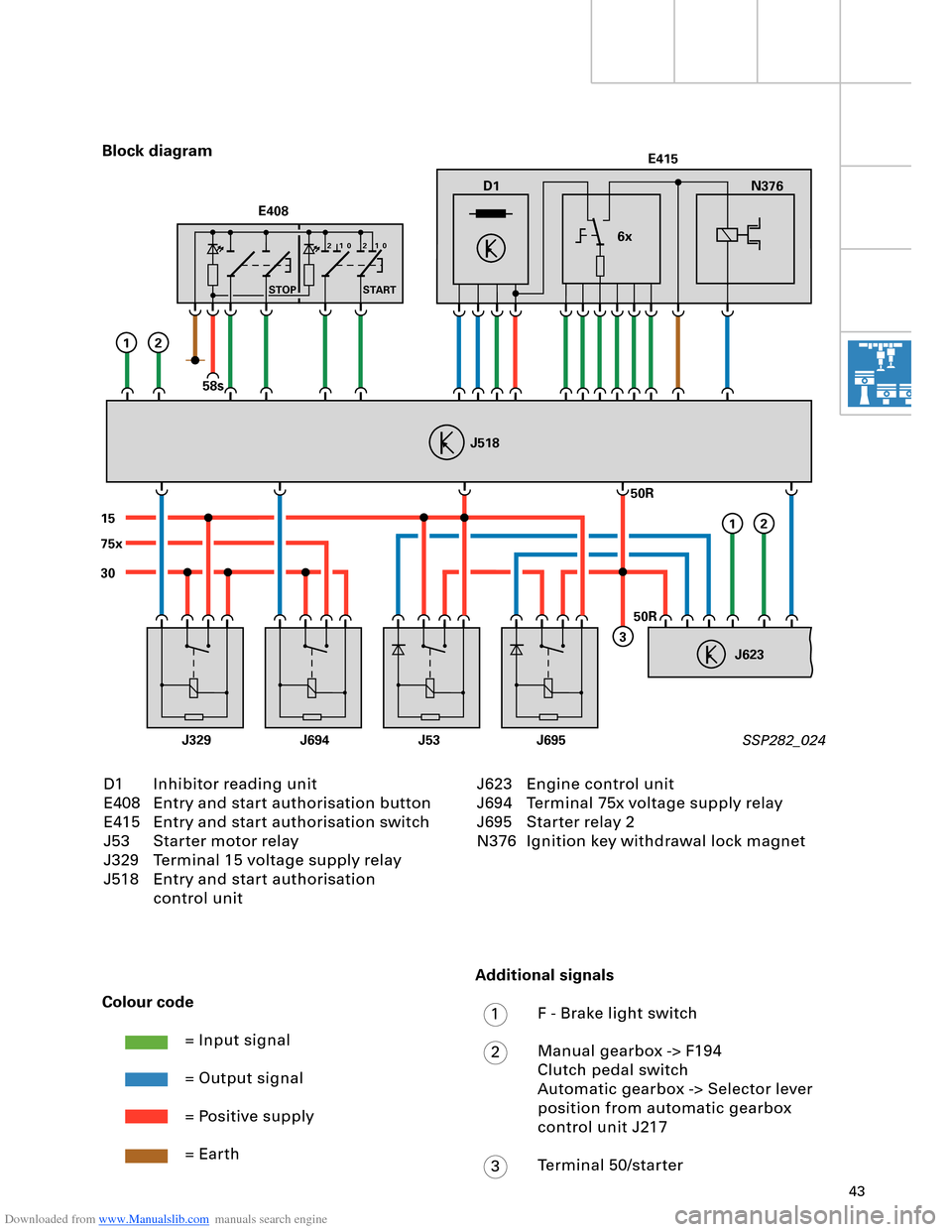
D1 Inhibitor reading unit
E408 Entry and start authorisation button
E415 Entry and start authorisation switch
J53 Starter motor relay
J329 Terminal 15 voltage supply relay
J518 Entry and start authorisation
control unit Block diagram
SSP282_024
Colour code
= Input signal
= Output signal
= Positive supply
= Earth
J623 Engine control unit
J694 Terminal 75x voltage supply relay
J695 Starter relay 2
N376 Ignition key withdrawal lock magnet
Additional signals
F - Brake light switch
Manual gearbox -> F194
Clutch pedal switch
Automatic gearbox -> Selector lever
position from automatic gearbox
control unit J217
Terminal 50/starter
1
2
3
Page 44 of 96
Downloaded from www.Manualslib.com manuals search engine 44
Engine, Mechanics
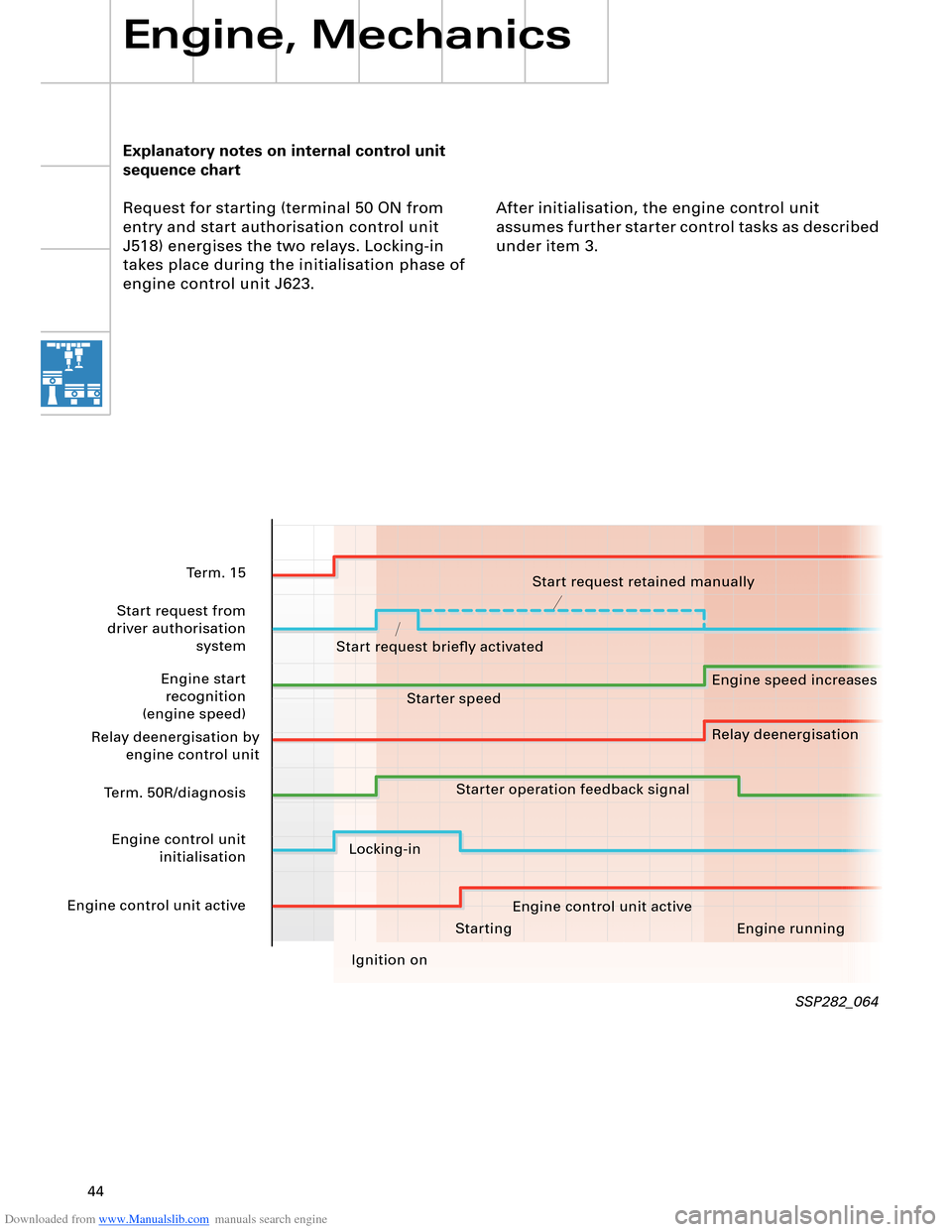
Explanatory notes on internal control unit
sequence chart
Request for starting (terminal 50 ON from
entry and start authorisation control unit
J518) energises the two relays. Locking-in
takes place during the initialisation phase of
engine control unit J623.After initialisation, the engine control unit
assumes further starter control tasks as described
under item 3.
SSP282_064
Starting Engine running
Ignition on
Term. 15
Start request from
driver authorisation system
Engine start recognition
(engine speed)
Relay deenergisation by engine control unit
Term. 50R/diagnosis
Engine control unit initialisation
Engine control unit active Start request retained manually
Start request briefly activated Engine speed increases
Relay deenergisation
Starter speed
Starter operation feedback signal
Locking-in Engine control unit active