2003 AUDI A8 CD changer
[x] Cancel search: CD changerPage 59 of 96
Downloaded from www.Manualslib.com manuals search engine 59SSP282_063
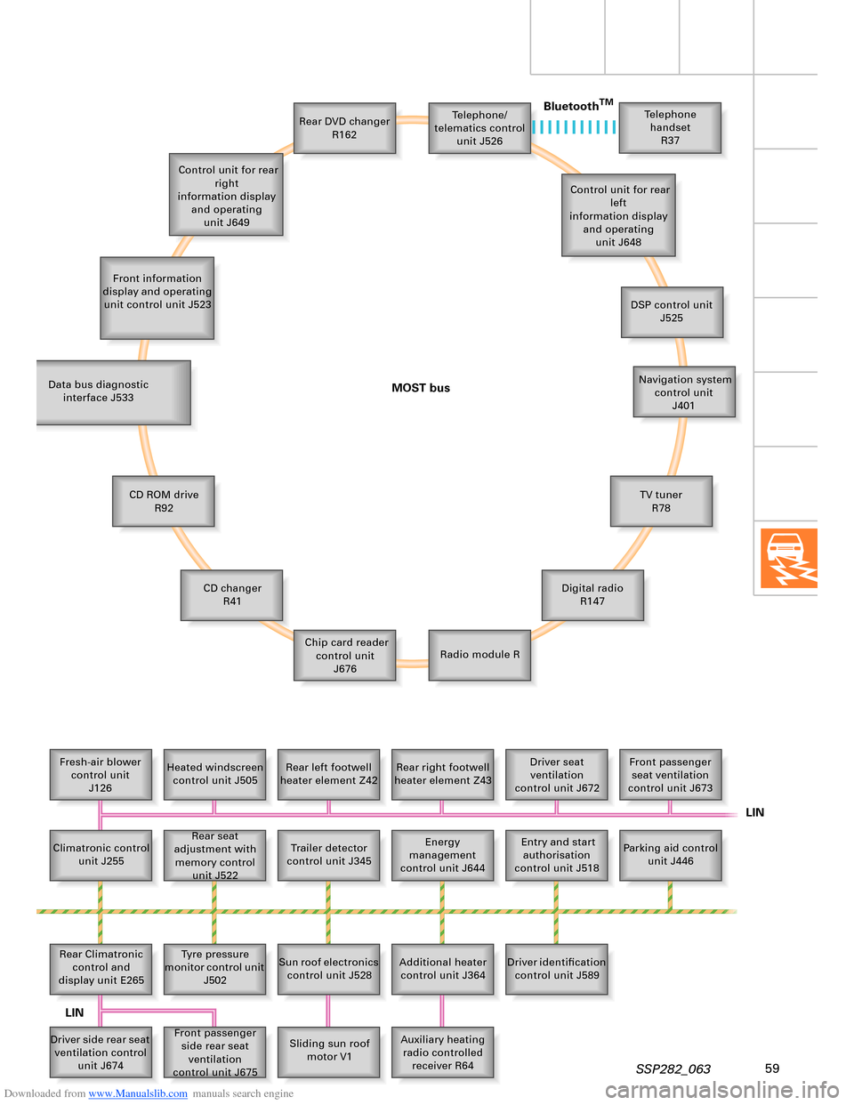
Telephone/
telematics control
unit J526
Front information
display and operating
unit control unit J523Rear DVD changer
R162Telephone
handset
R37
Control unit for rear
left
information display
and operating
unit J648
DSP control unit
J525
Navigation system
control unit
J401
TV tuner
R78
Digital radio
R147
Radio module R Chip card reader
control unit
J676 CD changer
R41 CD ROM drive
R92 Data bus diagnostic
interface J533
Fresh-air blower
control unit
J126Heated windscreen
control unit J505Rear left footwell
heater element Z42Rear right footwell
heater element Z43Driver seat
ventilation
control unit J672Front passenger
seat ventilation
control unit J673
Parking aid control
unit J446 Entry and start
authorisation
control unit J518 Energy
management
control unit J644 Rear seat
adjustment with
memory control
unit J522 Climatronic control
unit J255
Trailer detector
control unit J345
Rear Climatronic
control and
display unit E265Tyre pressure
monitor control unit
J502
Sun roof electronics
control unit J528
Additional heater
control unit J364Driver identification
control unit J589
Auxiliary heating
radio controlled
receiver R64 Sliding sun roof
motor V1 Front passenger
side rear seat
ventilation
control unit J675 Driver side rear seat
ventilation control
unit J674 Control unit for rear
right
information display
and operating
unit J649
MOST busBluetooth
TM
LIN
LIN
Page 65 of 96
Downloaded from www.Manualslib.com manuals search engine 65
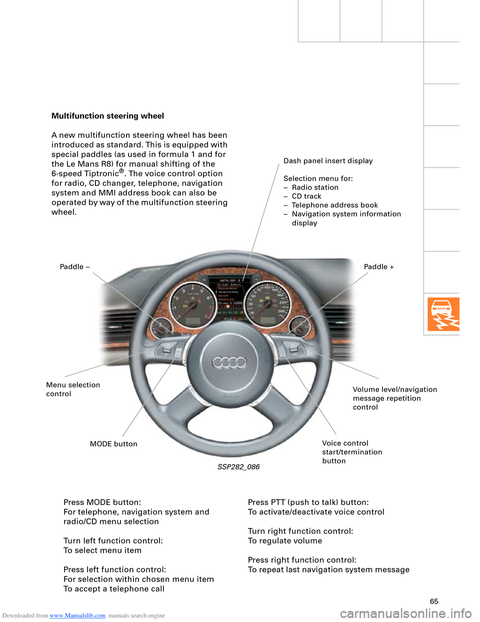
Multifunction steering wheel
A new multifunction steering wheel has been
introduced as standard. This is equipped with
special paddles (as used in formula 1 and for
the Le Mans R8) for manual shifting of the
6-speed Tiptronic
®. The voice control option
for radio, CD changer, telephone, navigation
system and MMI address book can also be
operated by way of the multifunction steering
wheel.
Dash panel insert display
Selection menu for:
– Radio station
– CD track
– Telephone address book
– Navigation system information
display
SSP282_086
Press MODE button:
For telephone, navigation system and
radio/CD menu selection
Turn left function control:
To select menu item
Press left function control:
For selection within chosen menu item
To accept a telephone callPress PTT (push to talk) button:
To activate/deactivate voice control
Turn right function control:
To regulate volume
Press right function control:
To repeat last navigation system message
Volume level/navigation
message repetition
control
Voice control
start/termination
button MODE button Menu selection
controlPaddle –Paddle +
Page 78 of 96
Downloaded from www.Manualslib.com manuals search engine 78
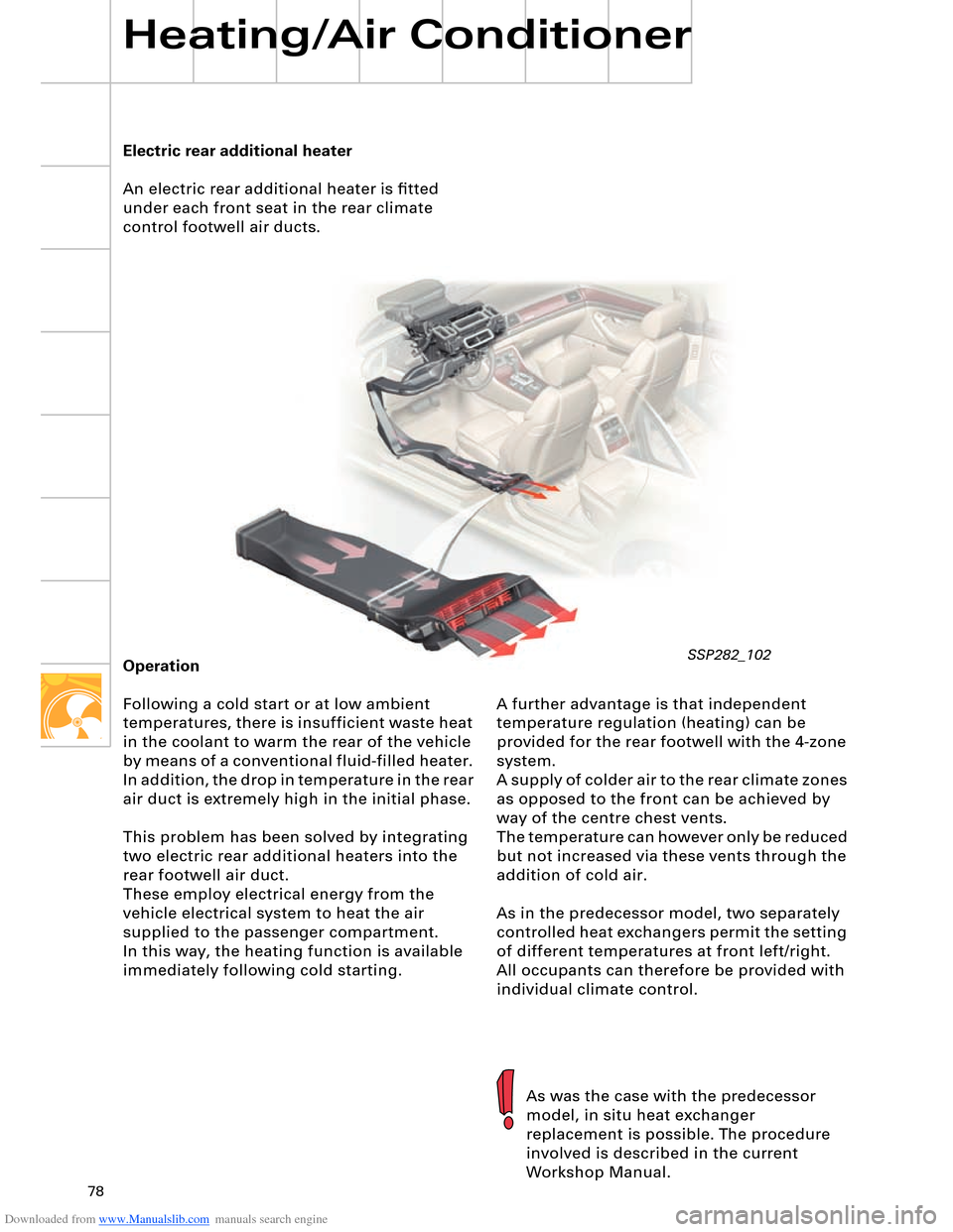
Electric rear additional heater
An electric rear additional heater is fitted
under each front seat in the rear climate
control footwell air ducts.
Heating/Air Conditioner
A further advantage is that independent
temperature regulation (heating) can be
provided for the rear footwell with the 4-zone
system.
A supply of colder air to the rear climate zones
as opposed to the front can be achieved by
way of the centre chest vents.
The temperature can however only be reduced
but not increased via these vents through the
addition of cold air.
As in the predecessor model, two separately
controlled heat exchangers permit the setting
of different temperatures at front left/right.
All occupants can therefore be provided with
individual climate control. Operation
Following a cold start or at low ambient
temperatures, there is insufficient waste heat
in the coolant to warm the rear of the vehicle
by means of a conventional fluid-filled heater.
In addition, the drop in temperature in the rear
air duct is extremely high in the initial phase.
This problem has been solved by integrating
two electric rear additional heaters into the
rear footwell air duct.
These employ electrical energy from the
vehicle electrical system to heat the air
supplied to the passenger compartment.
In this way, the heating function is available
immediately following cold starting.
As was the case with the predecessor
model, in situ heat exchanger
replacement is possible. The procedure
involved is described in the current
Workshop Manual.
SSP282_102
Page 82 of 96
Downloaded from www.Manualslib.com manuals search engine 82
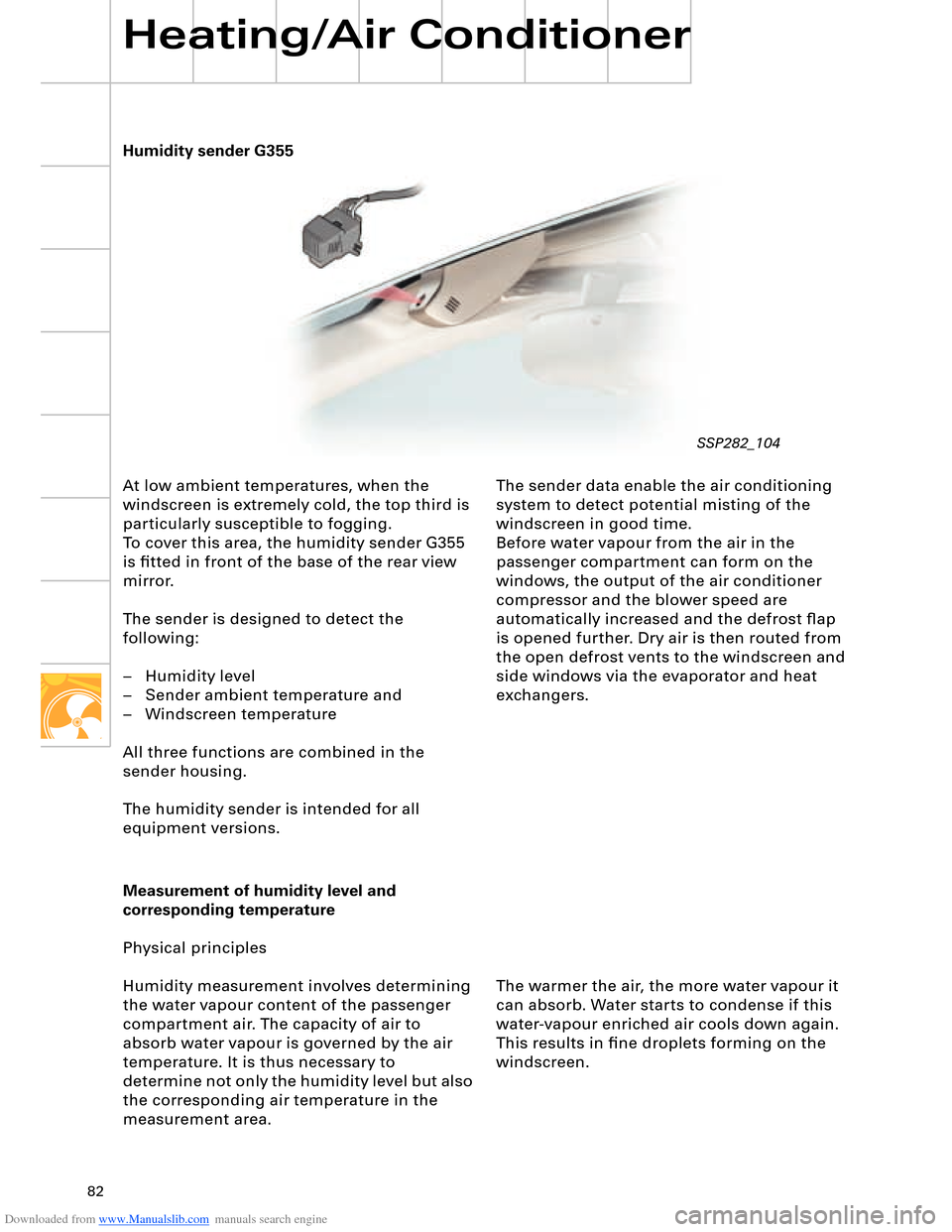
Humidity sender G355
Heating/Air Conditioner
At low ambient temperatures, when the
windscreen is extremely cold, the top third is
particularly susceptible to fogging.
To cover this area, the humidity sender G355
is fitted in front of the base of the rear view
mirror.
The sender is designed to detect the
following:
– Humidity level
– Sender ambient temperature and
– Windscreen temperature
All three functions are combined in the
sender housing.
The humidity sender is intended for all
equipment versions.The sender data enable the air conditioning
system to detect potential misting of the
windscreen in good time.
Before water vapour from the air in the
passenger compartment can form on the
windows, the output of the air conditioner
compressor and the blower speed are
automatically increased and the defrost flap
is opened further. Dry air is then routed from
the open defrost vents to the windscreen and
side windows via the evaporator and heat
exchangers.
Measurement of humidity level and
corresponding temperature
Physical principles
Humidity measurement involves determining
the water vapour content of the passenger
compartment air. The capacity of air to
absorb water vapour is governed by the air
temperature. It is thus necessary to
determine not only the humidity level but also
the corresponding air temperature in the
measurement area.The warmer the air, the more water vapour it
can absorb. Water starts to condense if this
water-vapour enriched air cools down again.
This results in fine droplets forming on the
windscreen.
SSP282_104
Page 91 of 96
Downloaded from www.Manualslib.com manuals search engine 91
4.2 Auxiliary heating sequence
The level of fuel in the tank is
interrogated. If the fuel tank is "empty",
the auxiliary heating function is not
permitted and the auxiliary heater symbol
in the dash panel insert goes out. "Empty"
roughly corresponds to the red display
zone. The energy management control
unit J644 checks whether there is
sufficient energy to accept auxiliary
heating. If this is the case, the auxiliary
heater is switched on in the various
operating modes depending on the
characteristic temperature curve and the
fresh-air blower is actuated.
If the auxiliary heating temperature
reaches a level of 30 °C, the fresh-air
blower is activated and the coolant
shutoff valve N279 pulsed in line with the
characteristic curve.
The auxiliary heater is switched off
automatically on completion of the operating
time transmitted by the MMI system to the
Climatronic control unit or it can be switched
off using the remote control OFF button.
Auxiliary heater circulation pump control
To speed up heating of the passenger
compartment and to achieve a better "heat
yield" in the air conditioner unit heat
exchanger, the circulation pump V55 and
coolant shutoff valve N279 are pulsed as a
function of water temperature and the
heating circuit flow rate is thus reduced.
An electric circulation pump is used for the
auxiliary heater. It is not possible to reduce
the supply voltage in the auxiliary heater
control unit and the circulation pump is thus
actuated at specific intervals to decrease its
output.
Additional control curve for "auxiliary heater"
and "additional heater"
When the engine is on, the auxiliary heater
and engine temperatures are constantly
compared. A switch to the large coolant
circuit is made as soon as the engine
temperature exceeds the auxiliary heater
temperature.
Activation of auxiliary heater circulation
pump with engine on
(pulsed operation of circulation pump)
In order to be able to ensure a sufficient flow
of water through the heat exchanger, the
auxiliary heater circulation pump must
additionally be switched on, as is the case for
instance with the 12-cylinder engine.If the engine is switched off again and not
all additional heater criteria (temperature,
time) are satisfied, the auxiliary heater
remains in operation for any residual
operating time before being deactivated.
This function can be encoded.
Page 92 of 96
Downloaded from www.Manualslib.com manuals search engine 92
Small coolant circuit with auxiliary heater
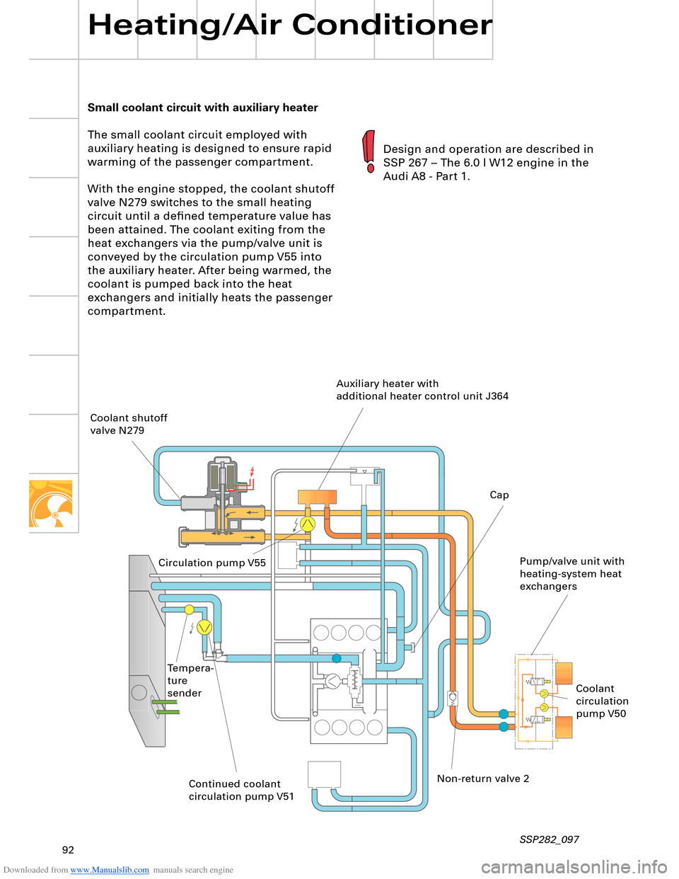
The small coolant circuit employed with
auxiliary heating is designed to ensure rapid
warming of the passenger compartment.
With the engine stopped, the coolant shutoff
valve N279 switches to the small heating
circuit until a defined temperature value has
been attained. The coolant exiting from the
heat exchangers via the pump/valve unit is
conveyed by the circulation pump V55 into
the auxiliary heater. After being warmed, the
coolant is pumped back into the heat
exchangers and initially heats the passenger
compartment.
Heating/Air Conditioner
SSP282_097
Design and operation are described in
SSP 267 – The 6.0 l W12 engine in the
Audi A8 - Part 1.
Coolant shutoff
valve N279
Circulation pump V55Auxiliary heater with
additional heater control unit J364
Non-return valve 2
Continued coolant
circulation pump V51 Tempera-
ture
senderPump/valve unit with
heating-system heat
exchangers Cap
Coolant
circulation
pump V50