Page 25 of 116
INSTRUMENT AND CONTROL FUNCTIONS
3-10
3
EAU00161
Brake lever The brake lever is located at the right
handlebar grip. To apply the front
brake, pull the lever toward the handle-
bar grip.The brake lever is equipped with a po-
sition adjusting dial. To adjust the dis-
tance between the brake lever and the
handlebar grip, turn the adjusting dial
while holding the lever pushed away
from the handlebar grip. Make sure that
the appropriate setting on the adjusting
dial is aligned with the arrow mark on
the brake lever.
EAU00162
Brake pedal The brake pedal is on the right side of
the motorcycle. To apply the rear
brake, press down on the brake pedal.
1. Brake lever
1. Brake lever position adjusting dial
2. Arrow mark
a. Distance between brake lever and handlebar
grip
1. Brake pedal
U5MTE1.book Page 10 Monday, August 6, 2001 6:10 PM
Page 26 of 116

INSTRUMENT AND CONTROL FUNCTIONS
3-11
3
EAU02935
Fuel tank cap To open the fuel tank cap
Open the fuel tank cap lock cover, in-
sert the key into the lock, and then turn
it 1/4 turn clockwise. The lock will be re-
leased and the fuel tank cap can be
opened.
To close the fuel tank cap
1. Push the fuel tank cap into posi-
tion with the key inserted in the
lock. 2. Turn the key counterclockwise to
the original position, remove it,
and then close the lock cover.
NOTE:@ The fuel tank cap cannot be closed un-
less the key is in the lock. In addition,
the key cannot be removed if the cap is
not properly closed and locked. @
EWA00025
WARNING
@ Make sure that the fuel tank cap is
properly closed before riding. @
EAU03753
Fuel Make sure that there is sufficient fuel in
the tank. Fill the fuel tank to the bottom
of the filler tube as shown.
EW000130
WARNING
_ �
Do not overfill the fuel tank, oth-
erwise it may overflow when the
fuel warms up and expands.
�
Avoid spilling fuel on the hot
engine.
_
1. Fuel tank cap lock cover
2. Unlock.
1. Fuel tank filler tube
2. Fuel level
U5MTE1.book Page 11 Monday, August 6, 2001 6:10 PM
Page 27 of 116

INSTRUMENT AND CONTROL FUNCTIONS
3-12
3
EAU00185
CAUTION:@ Immediately wipe off spilled fuel
with a clean, dry, soft cloth, since
fuel may deteriorate painted surfac-
es or plastic parts. @
EAU04255
ECA00104
CAUTION:_ Use only unleaded gasoline. The
use of leaded gasoline will cause se-
vere damage to internal engine
parts, such as the valves and piston
rings, as well as to the exhaust sys-
tem. _
Your Yamaha engine has been de-
signed to use regular unleaded gaso-
line with a research octane number of
91 or higher. If knocking (or pinging)
occurs, use a gasoline of a different
brand or premium unleaded fuel. Use
of unleaded fuel will extend spark plug
life and reduce maintenance costs.
EAU02955
Fuel tank breather hose Before operating the motorcycle:�
Check the fuel tank breather hose
connection.
�
Check the fuel tank breather hose
for cracks or damage, and replace
it if damaged.
�
Make sure that the end of the fuel
tank breather hose is not blocked,
and clean it if necessary. Recommended fuel:
REGULAR UNLEADED
GASOLINE ONLY
Fuel tank capacity:
Total amount:
17 L
Reserve amount:
3.5 L
1. Fuel tank breather hoseLeft side
U5MTE1.book Page 12 Monday, August 6, 2001 6:10 PM
Page 28 of 116
INSTRUMENT AND CONTROL FUNCTIONS
3-13
3
EAU02973
Starter (choke) lever “”Starting a cold engine requires a richer
air-fuel mixture, which is supplied by
the starter (choke).
Move the lever in direction
a to turn on
the starter (choke).
Move the lever in direction
b to turn off
the starter (choke).
ECA00038
CAUTION:@ Do not use the starter (choke) for
more than 3 minutes as the exhaust
pipe may discolor from excessive
heat. In addition, extended use of
the starter (choke) will cause after-
burning. If this occurs, turn off the
starter (choke). @
EAU03814
Seats Rider seat
To remove the rider seatPull up the rear corners of the rider seat
as shown, remove the bolts, and then
pull the seat off.
1. Starter (choke) lever “”
1. Bolt (× 2)
U5MTE1.book Page 13 Monday, August 6, 2001 6:10 PM
Page 29 of 116
INSTRUMENT AND CONTROL FUNCTIONS
3-14
3
To install the rider seat
Insert the projection on the front of the
rider seat into the seat holder as
shown, place the seat in the original
position, and then install the bolts.Passenger seat
To remove the passenger seat
1. Insert the key into the seat lock,
and then turn it counterclockwise.
2. While holding the key in that posi-
tion, lift the front of the passenger
seat and pull it forward.To install the passenger seat
1. Insert the projection on the rear of
the passenger seat into the seat
holder as shown, and then push
the front of the seat down to lock it
in place.
2. Remove the key.NOTE:_ Make sure that the seats are properly
secured before riding. _
1. Projection
2. Seat holder
1. Passenger seat lock
2. Unlock.Left side
1. Projection
2. Seat holder
U5MTE1.book Page 14 Monday, August 6, 2001 6:10 PM
Page 30 of 116

INSTRUMENT AND CONTROL FUNCTIONS
3-15
3
EAU03159
Helmet holders The helmet holders are located on the
bottom of the passenger seat.
To secure a helmet to a helmet hold-
er
1. Remove the passenger seat. (See
page 3-14 for removal and instal-
lation procedures.)
2. Attach the helmet to a helmet
holder, and then securely install
the passenger seat.
EWA00015
WARNING
_ Never ride with a helmet attached to
a helmet holder, since the helmet
may hit objects, causing loss of
control and possibly an accident. _To release the helmet from a helmet
holder
Remove the passenger seat, remove
the helmet from the helmet holder, and
then install the seat.
EAU03728
Storage compartment The storage compartment is located
under the passenger seat. (See
page 3-14 for passenger seat removal
and installation procedures.)
This storage compartment is designed
to hold a genuine Yamaha U-LOCK.
(Other locks may not fit.)
EWA00005
WARNING
_ �
Do not exceed the load limit of
3 kg for the storage compart-
ment.
�
Do not exceed the maximum
load of 189 kg for the vehicle.
_
1. Helmet holder (× 2)U5MTE1.book Page 15 Monday, August 6, 2001 6:10 PM
Page 31 of 116
INSTRUMENT AND CONTROL FUNCTIONS
3-16
3
To place a U-LOCK in the storage
compartment:
1. Remove the rubber cap from the
hole at the bottom of the storage
compartment, and then store it in a
safe place to prevent losing the
cap.
2. Insert the ends of the U-LOCK bar
into the holes at the bottom of the
storage compartment as shown.
3. Place the lock of the U-LOCK un-
der the curved part of the U-LOCK
bar as shown.4. Securely fasten the U-LOCK bar
and lock with the strap as shown.
NOTE:_ �
When the U-LOCK is not in the
storage compartment, be sure to
cover the hole at the bottom of the
storage compartment with the rub-
ber cap.
�
When storing items in the storage
compartment, be sure to wrap
them in a plastic bag to prevent
losing them.
_
1. Rubber cap
2. Owner’s tool kit
3. Hole (× 2)
4. U-LOCK bar (optional)
5. Lock of U-LOCK (optional)
6. Strap (× 2)
U5MTE1.book Page 16 Monday, August 6, 2001 6:10 PM
Page 32 of 116
INSTRUMENT AND CONTROL FUNCTIONS
3-17
3
EAU01862
Adjusting the front fork This front fork is equipped with spring
preload adjusting bolts, rebound damp-
ing force adjusting screws and com-
pression damping force adjusting
screws.
EW000035
WARNING
@ Always adjust both fork legs equal-
ly, otherwise poor handling and loss
of stability may result. @
Spring preload
To increase the spring preload and
thereby harden the suspension, turn
the adjusting bolt on each fork leg in di-
rection
a. To decrease the spring pre-
load and thereby soften the
suspension, turn the adjusting bolt on
each fork leg in direction
b.NOTE:@ Align the appropriate groove on the ad-
justing mechanism with the top of the
front fork cap bolt. @
CI-10E
1. Spring preload adjusting bolt
1. Current setting
2. Front fork cap bolt
Setting
Minimum (soft) 8
Standard 7
Maximum (hard) 1
U5MTE1.book Page 17 Monday, August 6, 2001 6:10 PM
 1
1 2
2 3
3 4
4 5
5 6
6 7
7 8
8 9
9 10
10 11
11 12
12 13
13 14
14 15
15 16
16 17
17 18
18 19
19 20
20 21
21 22
22 23
23 24
24 25
25 26
26 27
27 28
28 29
29 30
30 31
31 32
32 33
33 34
34 35
35 36
36 37
37 38
38 39
39 40
40 41
41 42
42 43
43 44
44 45
45 46
46 47
47 48
48 49
49 50
50 51
51 52
52 53
53 54
54 55
55 56
56 57
57 58
58 59
59 60
60 61
61 62
62 63
63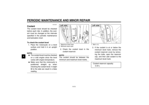 64
64 65
65 66
66 67
67 68
68 69
69 70
70 71
71 72
72 73
73 74
74 75
75 76
76 77
77 78
78 79
79 80
80 81
81 82
82 83
83 84
84 85
85 86
86 87
87 88
88 89
89 90
90 91
91 92
92 93
93 94
94 95
95 96
96 97
97 98
98 99
99 100
100 101
101 102
102 103
103 104
104 105
105 106
106 107
107 108
108 109
109 110
110 111
111 112
112 113
113 114
114 115
115
 lever “”Starting a cold engine requires a richer
air-fuel mixture, which is supplied by
the starter (choke).
Move the lever in dire")


