Page 538 of 776
4 - 98
ENGCRANKCASE AND CRANKSHAFT
EC4N4201
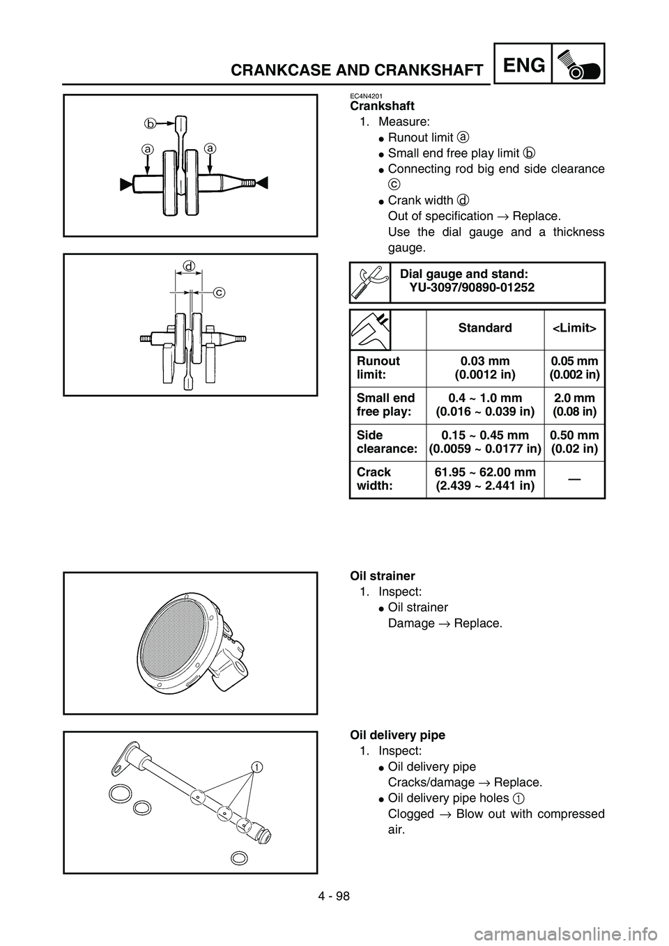
Crankshaft
1. Measure:
�Runout limit a
�Small end free play limit b
�Connecting rod big end side clearance
c
�Crank width d
Out of specification → Replace.
Use the dial gauge and a thickness
gauge.
Dial gauge and stand:
YU-3097/90890-01252
Standard
Runout
limit:0.03 mm
(0.0012 in)0.05 mm
(0.002 in)
Small end
free play:0.4 ~ 1.0 mm
(0.016 ~ 0.039 in)2.0 mm
(0.08 in)
Side
clearance:0.15 ~ 0.45 mm
(0.0059 ~ 0.0177 in)0.50 mm
(0.02 in)
Crack
width:61.95 ~ 62.00 mm
(2.439 ~ 2.441 in)—
Oil strainer
1. Inspect:
�Oil strainer
Damage → Replace.
Oil delivery pipe
1. Inspect:
�Oil delivery pipe
Cracks/damage → Replace.
�Oil delivery pipe holes 1
Clogged → Blow out with compressed
air.
Page 542 of 776
4 - 100
ENGCRANKCASE AND CRANKSHAFT
NOTE:
�Hold the connecting rod at top dead center
with one hand while turning the nut of the
installing tool with the other. Operate the
installing tool until the crankshaft bottoms
against the bearing.
�Before installing the crankshaft, clean the
contacting surface of crankcase.
CAUTION:
Do not use a hammer to drive in the crank-
shaft.
2. Check:
�Shifter operation
�Transmission operation
Unsmooth operation → Repair.
3. Install:
�Oil strainer 1
�Bolt (oil strainer) 2
T R..10 Nm (1.0 m · kg, 7.2 ft · lb)
4. Apply:
�Sealant
On the crankcase (right) 1.
NOTE:
Clean the contacting surface of crankcase (left
and right) before applying the sealant.
Quick gasket®:
ACC-QUICK-GS-KT
YAMAHA Bond No. 1215:
90890-85505
Page 544 of 776
4 - 101
ENGCRANKCASE AND CRANKSHAFT
5. Install:
�Dowel pin 1
�O-ring 2
�Crankcase (right)
To crankcase (left).
NOTE:
�Fit the crankcase (right) onto the crankcase
(left). Tap lightly on the case with soft ham-
mer.
�When installing the crankcase, the connect-
ing rod should be positioned at TDC (top
dead center).
6. Tighten:
�Hose guide 1
�Clutch cable holder 2
�Bolt (crankcase)
NOTE:
Tighten the crankcase tightening bolts in
stage, using a crisscross pattern.
7. Install:
�Oil delivery pipe
�O-ring
�Bolt (oil delivery pipe)
8. Install:
�Timing chain
�Timing chain guide (rear)
�Bolt (timing chain guide)
9. Remove:
�Sealant
Forced out on the cylinder mating sur-
face.
10. Apply:
�Engine oil
To the crank pin, bearing and oil deliv-
ery hole.
11. Check:
�Crankshaft and transmission operation.
Unsmooth operation → Repair.
New
T R..12 Nm (1.2 m · kg, 8.7 ft · lb)
New
T R..10 Nm (1.0 m · kg, 7.2 ft · lb)
T R..10 Nm (1.0 m · kg, 7.2 ft · lb)
Page 550 of 776
4 - 104
ENGTRANSMISSION, SHIFT CAM AND SHIFT FORK
EC4H4801
Shift fork, shift cam and segment
1. Inspect:
�Shift fork 1
Wear/damage/scratches → Replace.
2. Inspect:
�Shift cam 1
�Segment 2
Bend/wear/damage → Replace.
3. Check:
�Shift fork movement
Unsmooth operation → Replace shift
fork.
NOTE:
For a malfunctioning shift fork, replace not only
the shift fork itself but the two gears each adja-
cent to the shift fork.
ASSEMBLY AND INSTALLATION
Transmission
1. Install:
�5th pinion gear (25T) 1
�3rd pinion gear (16T) 2
�Collar 3
�4th pinion gear (20T) 4
�2nd pinion gear (15T) 5
To main axle 6.
NOTE:
�Apply the molybdenum disulfide oil on the
4th and 5th pinion gears inner circumference
and on the end surface.
�Apply the molybdenum disulfide oil on the
2nd and 3rd pinion gears inner circumfer-
ence.
Page 552 of 776
4 - 105
ENGTRANSMISSION, SHIFT CAM AND SHIFT FORK
2. Install:
�2nd wheel gear (26T) 1
�4th wheel gear (21T) 2
�3rd wheel gear (21T) 3
�5th wheel gear (21T) 4
�1st wheel gear (29T) 5
�O-ring 6
To drive axle 7.
NOTE:
�Apply the molybdenum disulfide oil on the
1st, 2nd and 3rd wheel gears inner circum-
ference and on the end surface.
�Apply the molybdenum disulfide oil on the
4th and 5th wheel gears inner circumfer-
ence.
�Apply the lithium soap base grease on the O-
ring.
3. Install:
�Plain washer 1
�Circlip 2
NOTE:
�Be sure the circlip sharp-edged corner a is
positioned opposite side to the plain washer
and gear b.
�Be sure the circlip end c is positioned at
axle spline groove d.
New
4. Install:
�Collar 1
NOTE:
�Apply the lithium soap base grease on the oil
seal lip.
�When installing the spacer into the crank-
case, pay careful attention to the crankcase
oil seal lip.
Page 554 of 776
4 - 106
ENG
TRANSMISSION, SHIFT CAM AND SHIFT FORK
5. Install:
�
Shift fork 1 (L)
1
�
Shift fork 2 (C)
2
�
Shift fork 3 (R)
3
�
Shift cam
4
To main axle and drive axle.
NOTE:
�
Apply the molybdenum disulfide oil on the
shift fork grooves.
�
Mesh the shift fork #1 (L) with the 4th wheel
gear
5
and #3 (R) with the 5th wheel gear
7
on the drive axle.
�
Mesh the shift fork #2 (C) with the 3rd pinion
gear
6
on the main axle.
6. Install:
�
Transmission assembly
1
To crankcase (left)
2
.
NOTE:
Apply the engine oil on the bearings and guide
bars.
7. Check:
�
Shifter operation
�
Transmission operation
Unsmooth operation
→
Repair.
Page 556 of 776
5 - 1
CHAS
EC500000
CHASSIS
EC590000
FRONT WHEEL AND REAR WHEEL
EC598000
FRONT WHEEL
Extent of removal:1 Front wheel removal2 Wheel bearing removal
3 Brake disc removal
Extent of removal Order Part name Q’ty Remarks
Preparation for removalFRONT WHEEL REMOVAL
Hold the machine by placing the
suitable stand under the engine.
WARNING
Support the machine securely so there is nodanger of it falling over.
1 Trip meter cable 1
2 Hose cover 1
3 Bolt (brake hose holder) 2 Only loosening.
4 Bolt (axle holder) 4 Only loosening.
5 Nut (front wheel axle) 1
6 Front wheel axle 1
7 Front wheel 1
8 Trip meter gear unit 1
9 Collar 1
10 Oil seal 1
11 Bearing 2 Refer to “REMOVAL POINTS”.
12 Brake disc 1
2
31
3
FRONT WHEEL AND REAR WHEEL
Page 558 of 776
5 - 2
CHAS
EC598100
REAR WHEEL
Extent of removal:1 Rear wheel removal2 Wheel bearing removal
3 Brake disc removal
Extent of removal Order Part name Q’ty Remarks
Preparation for removalREAR WHEEL REMOVAL
Hold the machine by placing the
suitable stand under the engine.
WARNING
Support the machine securely so there is nodanger of it falling over.
1 Nut (rear wheel axle) 1
2 Rear wheel axle 1
3 Chain puller 2
4 Rear wheel 1 Refer to “REMOVAL POINTS”.
5 Collar 2
6 Driven sprocket 1
7 Oil seal 2
8 Circlip 1
9 Bearing 2 Refer to “REMOVAL POINTS”.
10Brake disc
1
2
31
3
FRONT WHEEL AND REAR WHEEL


 5 - 1
CHAS
EC500000
CHASSIS
EC590000
FRONT WHEEL AND REAR WHEEL
EC598000
FRONT WHEEL
Extent of removal:1 Front wheel removal2 Wheel bearing removal
3 Brake disc removal
Extent of removal Order Part na")
 5 - 2
CHAS
EC598100
REAR WHEEL
Extent of removal:1 Rear wheel removal2 Wheel bearing removal
3 Brake disc removal
Extent of removal Order Part name Q’ty Remarks
Preparation for removalREAR WHEEL REM")