Page 76 of 694

WR250F (EUROPE)
WR250F(P) (CDN, AUS, NZ, ZA)
Model code number: 5PH5 (USA)
5")
SPEC
2 - 1
GENERAL SPECIFICATIONS
EC200000
SPECIFICATIONS
EC211000
GENERAL SPECIFICATIONS
Model name: WR250FP (USA)
WR250F (EUROPE)
WR250F(P) (CDN, AUS, NZ, ZA)
Model code number: 5PH5 (USA)
5PH6 (EUROPE)
5PH8 (CDN, AUS, NZ, ZA)
Dimensions:
Overall length 2,165 mm (85.2 in)
Overall width 827 mm (32.6 in)
Overall height 1,303 mm (51.3 in)
Seat height 998 mm (39.3 in)
Wheelbase 1,475 mm (58.1 in)
Minimum ground clearance 382 mm (15.0 in)
Basic weight:
With oil and full fuel tank 110.0 kg (242.5 lb)
Engine:
Engine type Liquid cooled 4-stroke, DOHC
Cylinder arrangement Single cylinder, forward inclined
Displacement 249 cm
3
(8.76 Imp oz, 8.42 US oz)
Bore
×
stroke 77.0
×
53.6 mm (3.03
×
2.11 in)
Compression ratio 12.5 : 1
Starting system Kickstarter
Lubrication system: Dry sump
Oil type or grade:
Engine oil (For USA and CDN)
At 5 ˚C (40 ˚F) or higher
Å
Yamalube 4 (20W-40) or SAE 20W-40 type
SH motor oil
(Non-Friction modified)
At 15 ˚C (60 ˚F) or lower
ı
Yamalube 4 (10W-30) or SAE 10W-30 type
SH motor oil
(Non-Friction modified)
and/or
Yamalube 4-R (15W-50)
(Non-Friction modified)
(Except for USA and CDN)
API “SH” or higher grade
-20
-4-10
140
3010
5020
6830
8640 50
104
122°CTemp.
°F
10W-30
10W-40
20W-40
20W-50
15W-40
2
Page 80 of 694

SPEC
2 - 5
MAINTENANCE SPECIFICATIONS
Timing chain:
Timing chain type/No. of links 92RH2010-114M/114 ----
Timing chain adjustment method Automatic ----
Valve, valve seat, valve guide:
Valve clearance (cold) IN 0.10 ~ 0.15 mm
(0.0039 ~ 0.0059 in)----
EX 0.17 ~ 0.22 mm
(0.0067 ~ 0.0087 in)----
Valve dimensions:
“A” head diameter IN 22.9 ~ 23.1 mm
(0.9016 ~ 0.9094 in)----
EX 24.4 ~ 24.6 mm
(0.9606 ~ 0.9685 in)----
“B” face width IN 2.26 mm (0.089 in) ----
EX 2.26 mm (0.089 in) ----
“C” seat width IN0.9 ~ 1.1 mm
(0.0354 ~ 0.0433 in)1.6 mm
(0.0630 in)
EX 0.9 ~ 1.1 mm
(0.0354 ~ 0.0433 in)1.6 mm
(0.0630 in)
“D” margin thickness IN 0.8 mm (0.0315 in) ----
EX 0.7 mm (0.0276 in) ----
Stem outside diameter IN3.975 ~ 3.990 mm
(0.1565 ~ 0.1571 in)3.945 mm
(0.1553 in)
EX 4.460 ~ 4.475 mm
(0.1756 ~ 0.1762 in)4.430 mm
(0.1744 in)
Guide inside diameter IN 4.000 ~ 4.012 mm
(0.1575 ~ 0.1580 in)4.050 mm
(0.1594 in)
EX 4.500 ~ 4.512 mm
(0.1772 ~ 0.1776 in)4.550 mm
(0.1791 in)
Stem-to-guide clearance IN0.010 ~ 0.037 mm
(0.0004 ~ 0.0015 in)0.08 mm
(0.003 in)
EX 0.025 ~ 0.052 mm
(0.0010 ~ 0.0020 in)0.10 mm
(0.004 in) Item Standard Limit
Head Diameter
B
Face WidthC
Seat Width
D
Margin ThicknessA
Page 81 of 694
SPEC
2 - 6
MAINTENANCE SPECIFICATIONS
Stem runout limit ---- 0.01 mm
(0.0004 in)
Valve seat width IN 0.9 ~ 1.1 mm
(0.0354 ~ 0.0433 in)1.6 mm
(0.0630 in)
EX 0.9 ~ 1.1 mm
(0.0354 ~ 0.0433 in)1.6 mm
(0.0630 in)
Valve spring:
Free length IN 37.81 mm (1.49 in) 35.9 mm
(1.41 in)
EX 37.54 mm (1.48 in) 35.7 mm
(1.41 in)
Set length (valve closed) IN 29.13 mm (1.15 in) ----
EX 29.30 mm (1.15 in) ----
Compressed pressure
(installed) IN 99 ~ 114 N
(10.1 ~ 11.6 kg, 22.27 ~ 25.57 lb)----
EX 126 ~ 144 N
(12.9 ~ 14.7 kg, 28.44 ~ 32.41 lb)----
Tilt limit IN ---- 2.5˚/ 1.7 mm
(2.5˚/0.067 in)
EX ---- 2.5˚/1.6 mm
(2.5˚/0.063 in)
Direction of winding
(top view) IN Clockwise ----
EX Clockwise ----
Piston:
Piston to cylinder clearance 0.040 ~ 0.065 mm
(0.0016 ~ 0.0026 in)0.1 mm
(0.004 in)
Piston size “D”76.955 ~ 76.970 mm
(3.0297 ~ 3.0303 in)----
Measuring point “H”8 mm (0.31 in) ----
Piston off-set 0.5 mm (0.020 in)/IN-side ----Item Standard Limit
*
H
D
Page 82 of 694
16.043 mm
(0.6316 in)
Piston pin outside diameter15.991 ~ 16.000 mm
(0.6296 ~ 0.6299")
SPEC
2 - 7
MAINTENANCE SPECIFICATIONS
Piston pin bore inside diameter16.002 ~ 16.013 mm
(0.6300 ~ 0.6304 in)16.043 mm
(0.6316 in)
Piston pin outside diameter15.991 ~ 16.000 mm
(0.6296 ~ 0.6299 in)15.971 mm
(0.6288 in)
Piston rings:
Top ring:
Type Barrel ----
Dimensions (B
×
T) 0.90
×
2.75 mm (0.04
×
0.11 in) ----
End gap (installed) 0.15 ~ 0.25 mm
(0.006 ~ 0.010 in)0.50 mm
(0.020 in)
Side clearance (installed) 0.030 ~ 0.065 mm
(0.0012 ~ 0.0026 in)0.12 mm
(0.005 in)
2nd ring:
Type Taper ----
Dimensions (B
×
T) 0.80
×
2.75 mm (0.03
×
0.11 in) ----
End gap (installed) 0.30 ~ 0.45 mm
(0.012 ~ 0.018 in)0.80 mm
(0.031 in)
Side clearance 0.020 ~ 0.055 mm
(0.0008 ~ 0.0022 in)0.12 mm
(0.005 in)
Oil ring:
Dimensions (B
×
T) 1.50
×
2.25 mm (0.06
×
0.09 in) ----
End gap (installed) 0.10 ~ 0.40 mm
(0.004 ~ 0.016 in)----
Crankshaft:
Crank width “A”55.95 ~ 56.00 mm
(2.203 ~ 2.205 in)----
Runout limit “C”0.03 mm (0.0012 in) 0.05 mm
(0.002 in)
Big end side clearance “D”0.15 ~ 0.45 mm
(0.0059 ~ 0.0177 in)0.50 mm
(0.02 in)
Small end free play “F”0.4 ~ 1.0 mm
(0.02 ~ 0.04 in)2.0 mm
(0.08 in)
Decompression device:
Type Manual ----
Cable free play 5 ~ 9 mm (0.20 ~ 0.35 in) ----Item Standard Limit
T
B
B
T
B
T
Page 84 of 694
SPEC
2 - 9
MAINTENANCE SPECIFICATIONS
Lubrication system:
Oil filter type Wire mesh type ----
Oil pump type Trochoid type ----
Tip clearance 0.12 mm or less
(0.0047 in or less)0.20 mm
(0.008 in)
Side clearance 0.09 ~ 0.17 mm
(0.0035 ~ 0.0067 in)0.24 mm
(0.009 in)
Housing and rotor clearance 0.03 ~ 0.10 mm
(0.0012 ~ 0.0039 in)0.17 mm
(0.0067 in)
Cooling:
Radiator core size
Width 117.8 mm (4.6 in) ----
Height 220 mm (8.7 in) ----
Thickness 32 mm (1.26 in) ----
Radiator cap opening pressure110 kPa (1.1 kg/cm
2
, 15.6 psi)----
Radiator capacity (total) 0.6 L (0.53 lmp qt, 0.63 US qt) ----
Water pump
Type Single-suction centrifugal pump ----Item Standard Limit
Page 318 of 694
.
Camshaft-to-cap clearance:
0.020 ~ 0.054 mm
(0.0008 ~ 0.0021 in)
<Limit>: 0.")
4 - 25
ENGCAMSHAFTS
4. Measure:
�Camshaft-to-cap clearance
Out of specification → Measure bearing
diameter (camshaft).
Camshaft-to-cap clearance:
0.020 ~ 0.054 mm
(0.0008 ~ 0.0021 in)
: 0.08 mm (0.003 in)
Measurement steps:
�Install the camshaft onto the cylinder
head.
�Position a strip of Plastigauge® 1 onto the
camshaft.
�Install the clip, dowel pins and camshaft
caps.
T R..
Bolt (camshaft cap):
10 Nm (1.0 m • kg, 7.2 ft • lb)
NOTE:
�Tighten the bolts (camshaft cap) in a criss-
cross pattern from innermost to outer
caps.
�Do not turn the camshaft when measuring
clearance with the Plastigauge®.
�Remove the camshaft caps and measure
the width of the Plastigauge
® 1.
5. Measure:
�Camshaft outside diameter a
Out of specification → Replace the
camshaft.
Within specification → Replace cam-
shaft case and camshaft caps as a set.
Camshaft sprocket
1. Inspect:
�Camshaft sprocket 1
Wear/damage → Replace the camshaft
assembly and timing chain as a set.
Camshaft outside diameter:
21.967 ~ 21.980 mm
(0.8648 ~ 0.8654 in)
1
Page 338 of 694
4 - 35
ENGVALVES AND VALVE SPRINGS
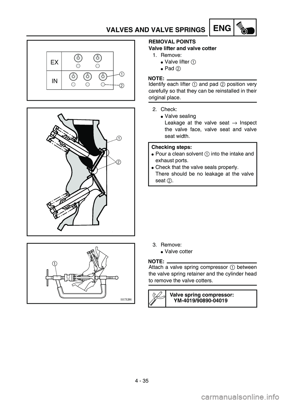
REMOVAL POINTS
Valve lifter and valve cotter
1. Remove:
�Valve lifter 1
�Pad 2
NOTE:
Identify each lifter 1 and pad 2 position very
carefully so that they can be reinstalled in their
original place.
2. Check:
�Valve sealing
Leakage at the valve seat → Inspect
the valve face, valve seat and valve
seat width.
Checking steps:
�Pour a clean solvent 1 into the intake and
exhaust ports.
�Check that the valve seals properly.
There should be no leakage at the valve
seat 2.
3. Remove:
�Valve cotter
NOTE:
Attach a valve spring compressor 1 between
the valve spring retainer and the cylinder head
to remove the valve cotters.
Valve spring compressor:
YM-4019/90890-04019
Page 344 of 694

Out of specification → Replace.
NOTE:
�When installing a new valve always replace
the guide.
�If the valve is removed or replaced")
4 - 38
ENGVALVES AND VALVE SPRINGS
5. Measure:
�Runout (valve stem)
Out of specification → Replace.
NOTE:
�When installing a new valve always replace
the guide.
�If the valve is removed or replaced always
replace the oil seal.
6. Eliminate:
�Carbon deposits
(from the valve face and valve seat)
7. Inspect:
�Valve seat
Pitting/wear → Reface the valve seat.
Runout limit:
0.01 mm (0.0004 in)
8. Measure:
�Valve seat width a
Out of specification → Reface the valve
seat.
Valve seat width:
Intake:
0.9 ~ 1.1 mm (0.0354 ~ 0.0433 in)
: 1.6 mm (0.0630 in)
Exhaust:
0.9 ~ 1.1 mm (0.0354 ~ 0.0433 in)
: 1.6 mm (0.0630 in)
Measurement steps:
�Apply Mechanic’s blueing dye (Dykem) b
to the valve face.
�Install the valve into the cylinder head.
�Press the valve through the valve guide
and onto the valve seat to make a clear
pattern.
�Measure the valve seat width. Where the
valve seat and valve face made contact,
blueing will have been removed.
�If the valve seat is too wide, too narrow, or
the seat is not centered, the valve seat
must be refaced.

Valve seat width IN 0.9 ~ 1.1 mm
(0.0354 ~ 0.0433 in)1.6 mm
(0.0630 in)
EX 0.9 ~ 1.1 mm
(0.0354 ~ 0.0433 in)1.6")
0.20 mm
(0.008 in)")