Page 6 of 94

EAU00009
TABLE OF CONTENTS
GIVE SAFETY THE RIGHT OF WAY ............... 1-1
DESCRIPTION .................................................. 2-1
Left view ......................................................... 2-1
Right view ...................................................... 2-2
Controls and instruments ............................... 2-3INSTRUMENT AND CONTROL FUNCTIONS
..... 3-1
Main switch/steering lock ............................... 3-1
Indicator and warning lights ........................... 3-2
Speedometer unit ........................................... 3-3
Tachometer .................................................... 3-3
Coolant temperature gauge ........................... 3-4
Handlebar switches ........................................ 3-4
Clutch lever .................................................... 3-6
Shift pedal ...................................................... 3-6
Brake lever ..................................................... 3-7
Brake pedal .................................................... 3-7
Fuel tank cap ................................................. 3-7
Fuel (except for Switzerland and Austria) ...... 3-8
Fuel (for Switzerland and Austria)................... 3-8
Catalytic converter
(for Switzerland and Austria) ........................ 3-9
2-stroke engine oil ........................................ 3-10
Fuel cock ...................................................... 3-11
Starter (choke) lever .................................... 3-12
Seat .............................................................. 3-12Helmet holder ............................................... 3-13
Adjusting the shock absorber assembly ........3-13
YEIS handling precautions ........................... 3-14
YPVS ........................................................... 3-15
Sidestand ..................................................... 3-15
Ignition circuit cut-off system ........................ 3-16
PRE-OPERATION CHECKS ............................ 4-1
Pre-operation check list ................................. 4-1
OPERATION AND IMPORTANT RIDING
POINTS ............................................................. 5-1
Starting a cold engine .................................... 5-1
Starting a warm engine .................................. 5-2
Shifting ........................................................... 5-3
Recommended shift points
(for Switzerland only) ................................... 5-3
Tips for reducing fuel consumption ............... 5-4
Engine break-in .............................................. 5-4
Parking ........................................................... 5-5
PERIODIC MAINTENANCE AND MINOR
REPAIR ............................................................. 6-1
Owner’s tool kit .............................................. 6-1
Periodic maintenance and lubrication chart ... 6-2
Removing and installing the cowlings and
panel ............................................................ 6-5
123
456
5AE-28199-E5 honbun 7/6/01 10:18 AM Page 5
Page 11 of 94
2-3
DESCRIPTION
2
1. Clutch lever (page 3-6, 6-20)
2. Left handlebar switches (page 3-4)
3. Speedometer unit (page 3-3)
4. Coolant temperature gauge (page 3-4)
5. Tachometer (page 3-3)6. Right handlebar switches (page 3-6)
7. Brake lever (page 3-7, 6-21)
8. Throttle grip (page 6-17, 6-28)
9. Fuel tank cap (page 3-7)
10. Main switch/steering lock (page 3-1)
1
2345
67
8 9
10
Controls and instruments
5AE-28199-E5 honbun 7/6/01 10:18 AM Page 10
Page 15 of 94

3-4
EAU01652
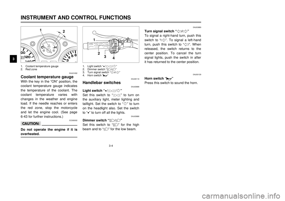
Coolant temperature gaugeWith the key in the “ON” position, the
coolant temperature gauge indicates
the temperature of the coolant. The
coolant temperature varies with
changes in the weather and engine
load. If the needle reaches or enters
the red zone, stop the motorcycle
and let the engine cool. (See page
6-43 for further instructions.)
EC000002
cCDo not operate the engine if it is
overheated.
EAU00118
Handlebar switches
EAU03898
Light switch “
9/
'
/:”
Set this switch to “'
” to turn on
the auxiliary light, meter lighting and
taillight. Set the switch to “:” to turn
on the headlight also. Set the switch
to “
9” to turn off all the lights.
EAU03888
Dimmer switch “&/%”
Set this switch to “&” for the high
beam and to “%” for the low beam.
EAU03889
Turn signal switch “4/6”
To signal a right-hand turn, push this
switch to “6”. To signal a left-hand
turn, push this switch to “4”. When
released, the switch returns to the
center position. To cancel the turn
signal lights, push the switch in after
it has returned to the center position.
EAU00129
Horn switch “*”
Press this switch to sound the horn.
INSTRUMENT AND CONTROL FUNCTIONS
3
2 1
1
2
3
4
1. Coolant temperature gauge
2. Red zone1. Light switch “
9/
'
/:”
2. Dimmer switch “&/%”
3. Turn signal switch “4/6”
4. Horn switch “*”
5AE-28199-E5 honbun 7/6/01 10:18 AM Page 14