2002 YAMAHA TDR 125 key
[x] Cancel search: keyPage 24 of 94
3-13
INSTRUMENT AND CONTROL FUNCTIONS
3
EAU00260
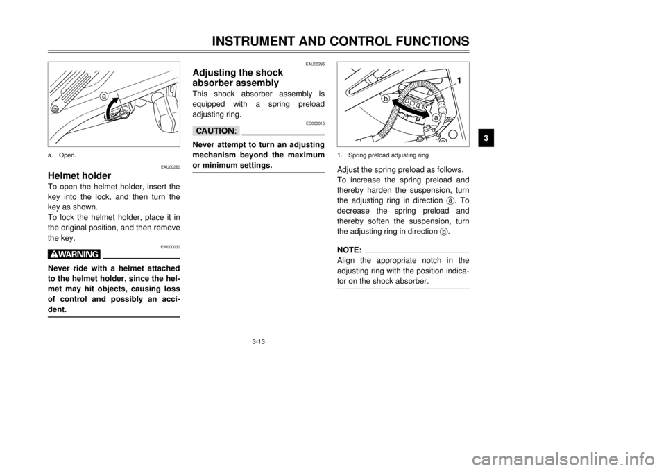
Helmet holderTo open the helmet holder, insert the
key into the lock, and then turn the
key as shown.
To lock the helmet holder, place it in
the original position, and then remove
the key.
EW000030
wNever ride with a helmet attached
to the helmet holder, since the hel-
met may hit objects, causing loss
of control and possibly an acci-
dent.
EAU00295
Adjusting the shock
absorber assemblyThis shock absorber assembly is
equipped with a spring preload
adjusting ring.
EC000015
cCNever attempt to turn an adjusting
mechanism beyond the maximum
or minimum settings.
Adjust the spring preload as follows.
To increase the spring preload and
thereby harden the suspension, turn
the adjusting ring in direction a. To
decrease the spring preload and
thereby soften the suspension, turn
the adjusting ring in direction b.NOTE:
Align the appropriate notch in the
adjusting ring with the position indica-
tor on the shock absorber.
a
a
b1
a. Open.1. Spring preload adjusting ring
5AE-28199-E5 honbun 7/6/01 10:18 AM Page 23
Page 26 of 94
3-15
INSTRUMENT AND CONTROL FUNCTIONS
3
EAU00326
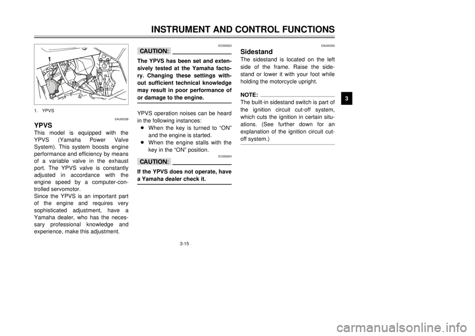
YPVSThis model is equipped with the
YPVS (Yamaha Power Valve
System). This system boosts engine
performance and efficiency by means
of a variable valve in the exhaust
port. The YPVS valve is constantly
adjusted in accordance with the
engine speed by a computer-con-
trolled servomotor.
Since the YPVS is an important part
of the engine and requires very
sophisticated adjustment, have a
Yamaha dealer, who has the neces-
sary professional knowledge and
experience, make this adjustment.
EC000023
cCThe YPVS has been set and exten-
sively tested at the Yamaha facto-
ry. Changing these settings with-
out sufficient technical knowledge
may result in poor performance of
or damage to the engine.YPVS operation noises can be heard
in the following instances:
8When the key is turned to “ON”
and the engine is started.
8When the engine stalls with the
key in the “ON” position.
EC000024
cCIf the YPVS does not operate, have
a Yamaha dealer check it.
EAU00330
SidestandThe sidestand is located on the left
side of the frame. Raise the side-
stand or lower it with your foot while
holding the motorcycle upright.NOTE:
The built-in sidestand switch is part of
the ignition circuit cut-off system,
which cuts the ignition in certain situ-
ations. (See further down for an
explanation of the ignition circuit cut-
off system.)
1
1. YPVS
5AE-28199-E5 honbun 7/6/01 10:18 AM Page 25
Page 28 of 94
3-17
INSTRUMENT AND CONTROL FUNCTIONS
3
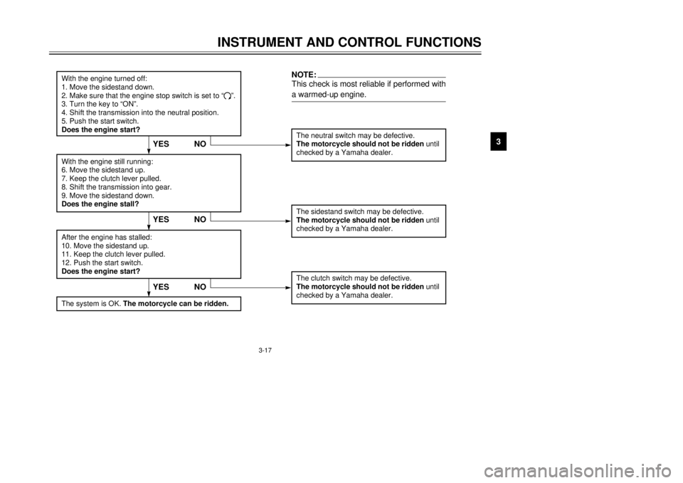
With the engine turned off:
1. Move the sidestand down.
2. Make sure that the engine stop switch is set to “
#”.
3. Turn the key to “ON”.
4. Shift the transmission into the neutral position.
5. Push the start switch.
Does the engine start?
The neutral switch may be defective.
The motorcycle should not be ridden until
checked by a Yamaha dealer.
With the engine still running:
6. Move the sidestand up.
7. Keep the clutch lever pulled.
8. Shift the transmission into gear.
9. Move the sidestand down.
Does the engine stall?After the engine has stalled:
10. Move the sidestand up.
11. Keep the clutch lever pulled.
12. Push the start switch.
Does the engine start?
The sidestand switch may be defective.
The motorcycle should not be ridden until
checked by a Yamaha dealer.The clutch switch may be defective.
The motorcycle should not be ridden until
checked by a Yamaha dealer.
NO
NOTE:This check is most reliable if performed with
a warmed-up engine.
YESYES NO
The system is OK. The motorcycle can be ridden.
YES NO
5AE-28199-E5 honbun 7/6/01 10:18 AM Page 27
Page 32 of 94

5-1
EAU00372
OPERATION AND IMPORTANT RIDING POINTS
5
EAU00373
w8Become thoroughly familiar
with all operating controls and
their functions before riding.
Consult a Yamaha dealer
regarding any control or func-
tion that you do not thorough-
ly understand.
8Never start the engine or oper-
ate it in a closed area for any
length of time. Exhaust fumes
are poisonous, and inhaling
them can cause loss of con-
sciousness and death within a
short time. Always make sure
that there is adequate ventila-
tion.
8Before starting out, make sure
that the sidestand is up. If the
sidestand is not raised com-
pletely, it could contact the
ground and distract the opera-
tor, resulting in a possible loss
of control.
EAU04271
Starting a cold engineIn order for the ignition circuit cut-off
system to enable starting, one of the
following conditions must be met:
8The transmission is in the neutral
position.
8The transmission is in gear with
the clutch lever pulled and the
sidestand up.
EW000054
w8Before starting the engine,
check the function of the igni-
tion circuit cut-off system
according to the procedure
described on page 3-17.
8Never ride with the sidestand
down.1. Turn the fuel cock lever to “ON”.
2. Turn the key to “ON” and make
sure that the engine stop switch
is set to “#”.3. Shift the transmission into the
neutral position.
NOTE:
When the transmission is in the neu-
tral position, the neutral indicator light
should be on, otherwise have a
Yamaha dealer check the electrical
circuit.4. Turn the starter (choke) on and
completely close the throttle.
(See page 3-12 for starter
(choke) operation.)
5. Start the engine by pushing the
start switch.NOTE:
If the engine fails to start, release the
start switch, wait a few seconds, and
then try again. Each starting attempt
should be as short as possible to pre-
serve the battery. Do not crank the
engine more than 10 seconds on any
one attempt.
5AE-28199-E5 honbun 7/6/01 10:18 AM Page 31
Page 36 of 94
5-5
OPERATION AND IMPORTANT RIDING POINTS
5 1,000 km and beyond
The vehicle can now be operated
normally.
EC000053
cC8Keep the engine speed out of
the tachometer red zone.
8If any engine trouble should
occur during the engine break-
in period, immediately have a
Yamaha dealer check the vehi-
cle.
EAU00458
ParkingWhen parking, stop the engine,
remove the key from the main switch,
and then turn the fuel cock lever to
“OFF”.
EW000058
w8Since the engine and exhaust
system can become very hot,
park in a place where pedestri-
ans or children are not likely
to touch them.
8Do not park on a slope or on
soft ground, otherwise the
motorcycle may overturn.
EC000062
cCNever park in an area where there
are fire hazards such as grass or
other flammable materials.
5AE-28199-E5 honbun 7/6/01 10:18 AM Page 35
Page 69 of 94
6-33
PERIODIC MAINTENANCE AND MINOR REPAIR
6To charge the battery
Have a Yamaha dealer charge the
battery as soon as possible if it
seems to have discharged. Keep in
mind that the battery tends to dis-
charge more quickly if the motorcycle
is equipped with optional electrical
accessories.
To store the battery
1. If the motorcycle will not be used
for more than one month,
remove the battery, fully charge
it, and then place it in a cool, dry
place.
2. If the battery will be stored for
more than two months, check it
at least once a month and fully
charge it if necessary.
3. Fully charge the battery before
installation.
4. After installation, make sure that
the battery leads are properly
connected to the battery termi-
nals.
EC000102
cC8Always keep the battery
charged. Storing a discharged
battery can cause permanent
battery damage.
8To charge a sealed-type (MF)
battery, a special (constant-
voltage) battery charger is
required. Using a conventional
battery charger will damage
the battery. If you do not have
access to a sealed-type (MF)
battery charger, have a
Yamaha dealer charge your
battery.
EAU01876
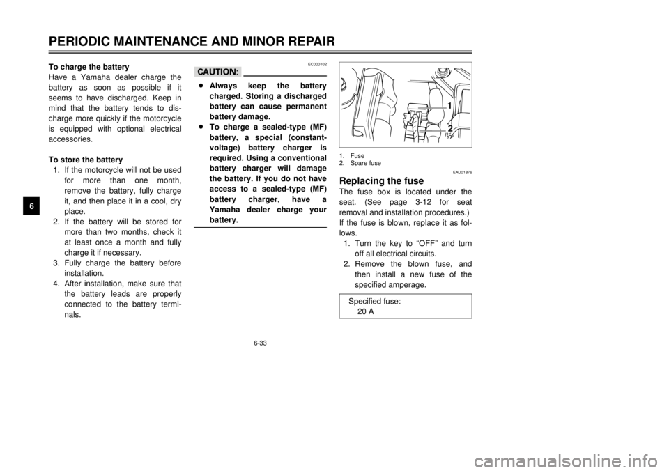
Replacing the fuseThe fuse box is located under the
seat. (See page 3-12 for seat
removal and installation procedures.)
If the fuse is blown, replace it as fol-
lows.
1. Turn the key to “OFF” and turn
off all electrical circuits.
2. Remove the blown fuse, and
then install a new fuse of the
specified amperage.
12
1. Fuse
2. Spare fuse
Specified fuse:
20 A
5AE-28199-E5 honbun 7/6/01 10:18 AM Page 68
Page 70 of 94

6-34
PERIODIC MAINTENANCE AND MINOR REPAIR
6
EC000103
cCDo not use a fuse of a higher
amperage rating than recommend-
ed to avoid causing extensive
damage to the electrical system
and possibly a fire.3. Turn the key to “ON” and turn on
the electrical circuits to check if
the devices operate.
4. If the fuse immediately blows
again, have a Yamaha dealer
check the electrical system.
EAU01079
Replacing a headlight bulbThis motorcycle is equipped with
quartz bulb headlights. If a headlight
bulb burns out, replace it as follows.
1. Remove cowling A. (See page
6-6 for cowling removal and
installation procedures.)
2. Disconnect the headlight cou-
pler, and then remove the head-
light bulb cover.
3. Remove the headlight bulb hold-
er according to the following
illustration, and then remove the
defective bulb.
NOTE:
The removal procedure depends on
the type of bulb holder installed on
your motorcycle.
EW000119
wHeadlight bulbs get very hot.
Therefore, keep flammable prod-
ucts away from a lit headlight bulb,
and do not touch the bulb until it
has cooled down.4. Place a new bulb into position,
and then secure it with the bulb
holder.
2
1
2
1
1. Headlight coupler
2. Headlight bulb cover
Type
1Type 2
Type 3Type 4 Turn
Unhook
UnhookTurn
5AE-28199-E5 honbun 7/6/01 10:18 AM Page 69
Page 90 of 94
9-1
EAU01039
CONSUMER INFORMATION
9
EAU02944
Identification numbersRecord the key identification number,
vehicle identification number and
model label information in the spaces
provided below for assistance when
ordering spare parts from a Yamaha
dealer or for reference in case the
vehicle is stolen.
1. KEY IDENTIFICATION
NUMBER:
2. VEHICLE IDENTIFICATION
NUMBER:
3. MODEL LABEL INFORMATION:
EAU01041
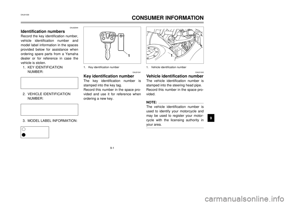
Key identification numberThe key identification number is
stamped into the key tag.
Record this number in the space pro-
vided and use it for reference when
ordering a new key.
EAU01043
Vehicle identification numberThe vehicle identification number is
stamped into the steering head pipe.
Record this number in the space pro-
vided.NOTE:
The vehicle identification number is
used to identify your motorcycle and
may be used to register your motor-
cycle with the licensing authority in
your area.
1
1
1. Key identification number 1. Vehicle identification number
1
6
5AE-28199-E5 honbun 7/6/01 10:18 AM Page 89