2002 YAMAHA MAJESTY 250 battery
[x] Cancel search: batteryPage 14 of 114

2-2
DESCRIPTION
2
9. Passenger seat
10. Rider seat (page 3-17)
11. Air flow louver (page 6-23)
12. Headlight (page 6-37)
13. Radiator 14. Battery (page 6-34)
15. Fuse box (page 6-36)
16. Coolant reservoir cap (page 6-19)
17. Coolant level check window (page 6-19)
18. Engine oil filler cap (page 6-15)
11
12
13 16 17
1815, 14
10
9
Right view
5SJ-28199-E0 1/24/02 6:14 PM Page 13
Page 18 of 114

3-2
INSTRUMENT AND CONTROL FUNCTIONS
3
EAU03733
.
(Parking)
The steering is locked, and the tail-
light, license light and auxiliary light
are on, but all other electrical sys-
tems are off. The key can be
removed.
To turn the main switch to “
.
”:
1. Turn the key to “LOCK”.
2. Slightly turn the key counter-
clockwise until it stops.
3. While still turning the key coun-
terclockwise, push it in until it
snaps into place.
ECA00043
cCDo not use the parking position for
an extended length of time, other-
wise the battery may discharge.
EAU03734
Oil change indicator light “
7
”
Oil change indicator lightThis indicator light comes on at the
initial 1,000 km and every 3,000 km
thereafter to indicate that the engine
oil should be changed.
If the engine oil is changed before the
oil change indicator comes on (i.e.
before the periodic oil change interval
has been reached), the indicator light
must be reset after the oil change for
the next periodic oil change to be
indicated at the correct time. (See
page 6-17 for the resetting proce-
dure.)
The electrical circuit of the indicator
light can be checked according to the
following procedure.
1. Set the engine stop switch to “#”
and turn the key to “ON”.
2. Check that the indicator comes
on for a few seconds and then
goes off.
3. If the indicator light does not
come on, have a Yamaha dealer
check the electrical circuit.
EAU00056
Indicator lightsIndicator lights
EAU04121
Turn signal indicator lights “4”
and “6”Turn signal indicator lightsThe corresponding indicator light
flashes when the turn signal switch is
pushed to the left or right.
EAU00063
High beam indicator light “&”High beam indicator lightThis indicator light comes on when
the high beam of the headlight is
switched on.
1
2
3
4
1. Left turn signal indicator light “4”
2. High beam indicator light “&”
3. Oil change indicator light “
7
”
4. Right turn signal indicator light “6”
5SJ-28199-E0 1/24/02 6:14 PM Page 17
Page 21 of 114

3-5
INSTRUMENT AND CONTROL FUNCTIONS
3
EAU03124
Coolant temperature gaugeCoolant temperature gaugeThis gauge indicates the coolant tem-
perature when the main switch is on.
The engine operating temperature
will vary with changes in weather and
engine load. If the needle points to
the red mark, stop your scooter and
let the engine cool. (See page
6-19 for details.)
EC000002
cCDo not operate the engine if it is
overheated.
1
2
1. Coolant temperature gauge
2. Red mark
EAU04589
Multi-function displayDisplay, multi-functionThe multi-function display is
equipped with the following:
8a tripmeter (which shows the dis-
tance traveled since it was last
set to zero)
8a fuel tripmeter (which shows the
distance traveled when the fuel
level reaches approximately 2.0 L)
8an odometer (which shows the
total distance traveled)
8a clock
8an outside temperature display8a voltage display (which shows
the battery voltage)
NOTE:
8When the key is turned to “ON”,
all segments of the display come
on for a few seconds. During this
time, the multi-function display is
performing a self-test.
8Be sure to turn the key to “ON”
before using the “SELECT” and
“RESET” buttons.
1
23
1. Tripmeter
2. Odometer, fuel tripmeter
3. Clock, outside temperature and voltage
meter display
5SJ-28199-E0 1/24/02 6:14 PM Page 20
Page 25 of 114

3-9
INSTRUMENT AND CONTROL FUNCTIONS
3
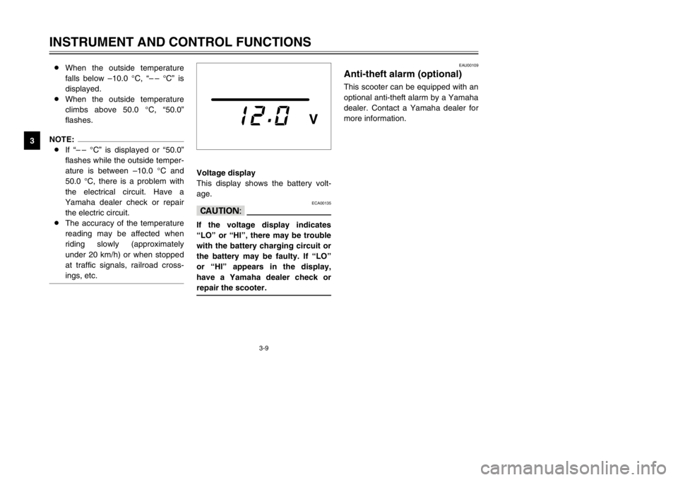
Voltage display
This display shows the battery volt-
age.
ECA00135
cCIf the voltage display indicates
“LO” or “HI”, there may be trouble
with the battery charging circuit or
the battery may be faulty. If “LO”
or “HI” appears in the display,
have a Yamaha dealer check or
repair the scooter.
EAU00109
Anti-theft alarm (optional)Anti-theft alarm (optional)This scooter can be equipped with an
optional anti-theft alarm by a Yamaha
dealer. Contact a Yamaha dealer for
more information. 8When the outside temperature
falls below –10.0 °C, “– – °C” is
displayed.
8When the outside temperature
climbs above 50.0 °C, “50.0”
flashes.
NOTE:
8If “– – °C” is displayed or “50.0”
flashes while the outside temper-
ature is between –10.0 °C and
50.0 °C, there is a problem with
the electrical circuit. Have a
Yamaha dealer check or repair
the electric circuit.
8The accuracy of the temperature
reading may be affected when
riding slowly (approximately
under 20 km/h) or when stopped
at traffic signals, railroad cross-
ings, etc.
5SJ-28199-E0 1/24/02 6:14 PM Page 24
Page 35 of 114

3-19
INSTRUMENT AND CONTROL FUNCTIONS
3
ECA00051
cCDo not leave the rider seat open
for an extended period of time,
otherwise the light may cause the
battery to discharge.
EWA00035
wDo not exceed the following load-
ing limits:
8 8
Front storage compartment A:
2 kg
8 8
Rear storage compartment:
5 kg
8 8
Maximum load for the vehicle:
185 kg
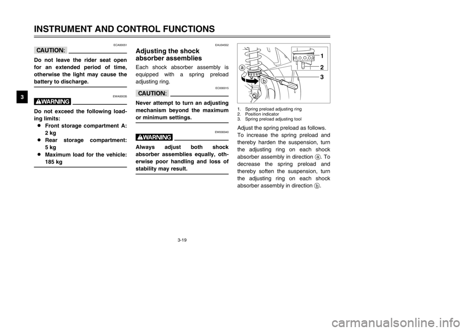
Adjust the spring preload as follows.
To increase the spring preload and
thereby harden the suspension, turn
the adjusting ring on each shock
absorber assembly in direction a. To
decrease the spring preload and
thereby soften the suspension, turn
the adjusting ring on each shock
absorber assembly in direction b.a
b1
23
1. Spring preload adjusting ring
2. Position indicator
3. Spring preload adjusting tool
EAU04552
Adjusting the shock
absorber assembliesShock absorber assemblies, adjustingEach shock absorber assembly is
equipped with a spring preload
adjusting ring.
EC000015
cCNever attempt to turn an adjusting
mechanism beyond the maximum
or minimum settings.
EW000040
wAlways adjust both shock
absorber assemblies equally, oth-
erwise poor handling and loss of
stability may result.
5SJ-28199-E0 1/24/02 6:14 PM Page 34
Page 46 of 114

5-2
OPERATION AND IMPORTANT RIDING POINTS
5
NOTE:
If the engine does not start, release
the start switch, wait a few seconds,
and then try again. Each starting
attempt should be as short as possi-
ble to preserve the battery. Do not
crank the engine more than 10 sec-
onds on any one attempt. If the
engine does not start, try with the
throttle open 1/8 turn.
ECA00045
cCFor maximum engine life, never
accelerate hard when the engine is
cold!
4. Check for oncoming traffic, and
then slowly turn the throttle grip
(on the right) in order to take off.
5. Switch the turn signal off.
EAU00433
Starting offStarting offNOTE:
Before starting off, allow the engine
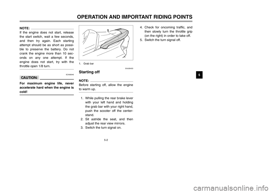
to warm up.1. While pulling the rear brake lever
with your left hand and holding
the grab bar with your right hand,
push the scooter off the center-
stand.
2. Sit astride the seat, and then
adjust the rear view mirrors.
3. Switch the turn signal on.
1
1. Grab bar
5SJ-28199-E0 1/24/02 6:14 PM Page 45
Page 50 of 114

PERIODIC MAINTENANCE AND MINOR REPAIR
Owner’s tool kit ......................................................6-1
Periodic maintenance and lubrication chart ..........6-3
Removing and installing the cowlings and panel ...6-6
Checking the spark plug ......................................6-12
Engine oil .............................................................6-14
Final transmission oil ...........................................6-18
Coolant ................................................................6-19
Air filter and V-belt case air filter elements ..........6-21
Air flow louver ......................................................6-23
Adjusting the throttle cable free play ...................6-23
Adjusting the valve clearance ..............................6-23
Tires ....................................................................6-24
Cast wheels .........................................................6-26
Adjusting the front and rear brake lever
free play .............................................................6-27
Checking the front and rear brake pads ..............6-28
Checking the brake fluid level .............................6-29
Changing the brake fluid .....................................6-30
Checking and lubricating the cables ....................6-30
Checking and lubricating the throttle grip
and cable ...........................................................6-31
Lubricating the front and rear brake levers ..........6-31
Checking and lubricating the centerstand
and sidestand ....................................................6-31Checking the front fork ........................................6-32
Checking the steering ..........................................6-33
Checking the wheel bearings ..............................6-33
Removing the battery cover ................................6-34
Battery .................................................................6-34
Replacing the fuses .............................................6-36
Replacing a headlight bulb ..................................6-37
Replacing a front turn signal light bulb ................6-39
Replacing a rear turn signal light bulb .................6-40
Replacing a tail/brake light bulb ..........................6-40
Replacing the license plate light bulb ..................6-41
Troubleshooting ...................................................6-42
Troubleshooting charts ........................................6-43
6
5SJ-28199-E0 1/24/02 6:14 PM Page 49
Page 69 of 114

6-19
PERIODIC MAINTENANCE AND MINOR REPAIR
67. Check the final transmission
case for oil leakage. If oil is leak-
ing, check for the cause.
EAU04591
CoolantCoolantThe coolant reservoir is located
under the battery cover. (See page
6-34 for battery cover removal and
installation procedures.)
To check the coolant level
1. Place the scooter on a level sur-
face and hold it in an upright
position.NOTE:
8The coolant level must be
checked on a cold engine since
the level varies with engine tem-
perature.
8Make sure that the scooter is
positioned straight up when
checking the coolant level. A
slight tilt to the side can result in
a false reading.
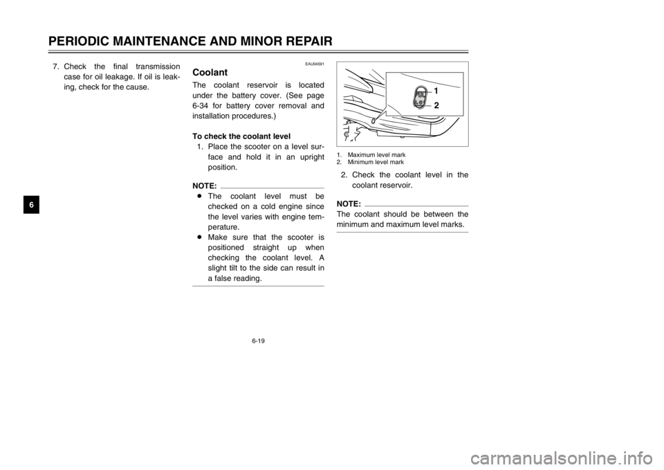
2. Check the coolant level in the
coolant reservoir.NOTE:
The coolant should be between the
minimum and maximum level marks.
1
2
1. Maximum level mark
2. Minimum level mark
5SJ-28199-E0 1/24/02 6:14 PM Page 68