2002 YAMAHA MAJESTY 250 coolant temperature
[x] Cancel search: coolant temperaturePage 15 of 114

2-3
EAU00026
DESCRIPTION
2
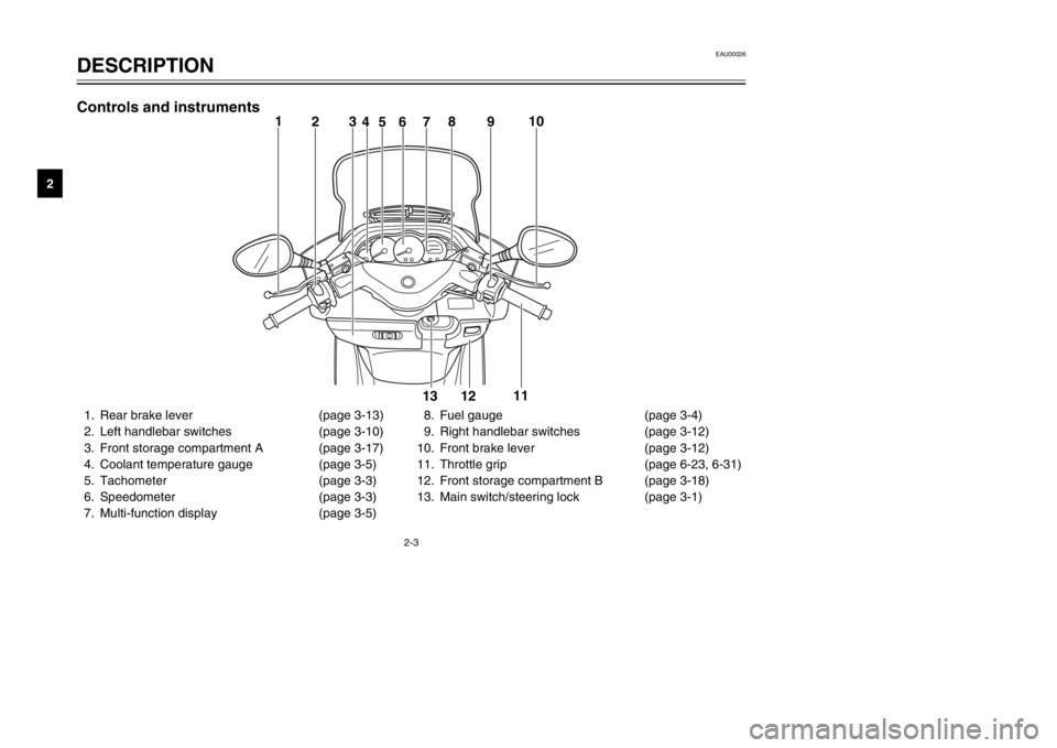
1. Rear brake lever (page 3-13)
2. Left handlebar switches (page 3-10)
3. Front storage compartment A (page 3-17)
4. Coolant temperature gauge (page 3-5)
5. Tachometer (page 3-3)
6. Speedometer (page 3-3)
7. Multi-function display (page 3-5)8. Fuel gauge (page 3-4)
9. Right handlebar switches (page 3-12)
10. Front brake lever (page 3-12)
11. Throttle grip (page 6-23, 6-31)
12. Front storage compartment B (page 3-18)
13. Main switch/steering lock (page 3-1)
1
23
46578910
11
12 13
Controls and instruments
5SJ-28199-E0 1/24/02 6:14 PM Page 14
Page 16 of 114

INSTRUMENT AND CONTROL FUNCTIONSMain switch/steering lock ...................................................................3-1
Indicator lights ...................................................................................3-2
Speedometer .....................................................................................3-3
Tachometer .......................................................................................3-3
Fuel gauge .........................................................................................3-4
Coolant temperature gauge ...............................................................3-5
Multi-function display .........................................................................3-5
Anti-theft alarm (optional) ..................................................................3-9
Handlebar switches .........................................................................3-10
Front brake lever .............................................................................3-12
Rear brake lever ..............................................................................3-13
Fuel tank cap ...................................................................................3-13
Fuel ..................................................................................................3-14
Catalytic converter ...........................................................................3-15
Rider seat ........................................................................................3-16
Adjusting the rider seat ....................................................................3-17
Storage compartments ....................................................................3-17
Adjusting the shock absorber assemblies .......................................3-19
Sidestand .........................................................................................3-20
Ignition circuit cut-off system ...........................................................3-21
3
5SJ-28199-E0 1/24/02 6:14 PM Page 15
Page 21 of 114

3-5
INSTRUMENT AND CONTROL FUNCTIONS
3
EAU03124
Coolant temperature gaugeCoolant temperature gaugeThis gauge indicates the coolant tem-
perature when the main switch is on.
The engine operating temperature
will vary with changes in weather and
engine load. If the needle points to
the red mark, stop your scooter and
let the engine cool. (See page
6-19 for details.)
EC000002
cCDo not operate the engine if it is
overheated.
1
2
1. Coolant temperature gauge
2. Red mark
EAU04589
Multi-function displayDisplay, multi-functionThe multi-function display is
equipped with the following:
8a tripmeter (which shows the dis-
tance traveled since it was last
set to zero)
8a fuel tripmeter (which shows the
distance traveled when the fuel
level reaches approximately 2.0 L)
8an odometer (which shows the
total distance traveled)
8a clock
8an outside temperature display8a voltage display (which shows
the battery voltage)
NOTE:
8When the key is turned to “ON”,
all segments of the display come
on for a few seconds. During this
time, the multi-function display is
performing a self-test.
8Be sure to turn the key to “ON”
before using the “SELECT” and
“RESET” buttons.
1
23
1. Tripmeter
2. Odometer, fuel tripmeter
3. Clock, outside temperature and voltage
meter display
5SJ-28199-E0 1/24/02 6:14 PM Page 20
Page 70 of 114

6-20
PERIODIC MAINTENANCE AND MINOR REPAIR
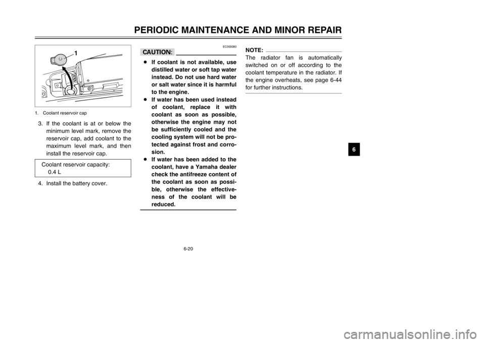
6 3. If the coolant is at or below the
minimum level mark, remove the
reservoir cap, add coolant to the
maximum level mark, and then
install the reservoir cap.
4. Install the battery cover.
1
1. Coolant reservoir cap
Coolant reservoir capacity:
0.4 L
EC000080
cC8If coolant is not available, use
distilled water or soft tap water
instead. Do not use hard water
or salt water since it is harmful
to the engine.
8If water has been used instead
of coolant, replace it with
coolant as soon as possible,
otherwise the engine may not
be sufficiently cooled and the
cooling system will not be pro-
tected against frost and corro-
sion.
8If water has been added to the
coolant, have a Yamaha dealer
check the antifreeze content of
the coolant as soon as possi-
ble, otherwise the effective-
ness of the coolant will be
reduced.
NOTE:
The radiator fan is automatically
switched on or off according to the
coolant temperature in the radiator. If
the engine overheats, see page 6-44
for further instructions.
5SJ-28199-E0 1/24/02 6:14 PM Page 69
Page 111 of 114

INDEX
F
Final transmission oil ............................6-18
Front and rear brake lever free play,
adjusting ............................................6-27
Front fork, checking ..............................6-32
Fuel ......................................................3-14
Fuel consumption, tips for reducing .......5-4
Fuel gauge .............................................3-4
Fuel tank cap ........................................3-13
Fuses, replacing ...................................6-36
H
Handlebar switches ..............................3-10
Dimmer switch ...................................3-10
Engine stop switch .............................3-12
Headlight variations ...........................3-11
Horn switch ........................................3-10
Pass switch ........................................3-10
Start switch ........................................3-12
Turn signal switch ..............................3-10
Headlight bulb, replacing ......................6-37
I
Identification numbers ............................9-1
Ignition circuit cut-off system ................3-21
Indicator lights ........................................3-2
High beam indicator light .....................3-2
Oil change indicator light .....................3-2
Turn signal indicator lights ...................3-2
K
Key identification number .......................9-1
L
License plate light bulb, replacing ........6-41
M
Main switch/steering lock .......................3-1
Model label .............................................9-2
P
Parking ...................................................5-5
Part locations ..........................................2-1
Periodic maintenance and lubrication
chart .....................................................6-3
Pre-operation check list ..........................4-1
R
Rider seat .............................................3-16
Rider seat, adjusting .............................3-17
S
Safe-riding points ...................................1-2
Shock absorber assemblies,
adjusting ............................................3-19
Sidestand .............................................3-20
Spark plug, checking ............................6-12
Specifications .........................................8-1
Speedometer ..........................................3-3
Starting off ..............................................5-2
Starting the engine .................................5-1
Steering, checking ................................6-33
Storage ...................................................7-4
Storage compartments .........................3-17
A
Acceleration and deceleration ................5-3
Air filter and V-belt case air filter
elements, cleaning .............................6-21
Air flow louver .......................................6-23
Anti-theft alarm (optional) .......................3-9
B
Battery ..................................................6-34
Battery cover removal ..........................6-34
Brake fluid level, checking ....................6-29
Brake fluid, changing ............................6-30
Brake lever, front ..................................3-12
Brake lever, rear ...................................3-13
Brake levers, lubricating .......................6-31
Braking ...................................................5-3
C
Cables, checking and lubricating ..........6-30
Care ........................................................7-1
Catalytic converter ................................3-15
Centerstand and sidestand, checking
and lubricating ...................................6-31
Conversion table ....................................8-5
Coolant .................................................6-19
Coolant temperature gauge ....................3-5
Cowlings and panel, removing and
installing ...............................................6-6
E
Engine break-in ......................................5-4
Engine oil ..............................................6-14
5SJ-28199-E0 1/24/02 6:14 PM Page 110