Page 16 of 96

INSTRUMENT AND CONTROL FUNCTIONS
2
1
54 3
1
2
6 5 4
3
EAU00063
High beam indicator light “1”
This indicator light comes on when the
high beam of the headlight is switched on.
EAUB0002
Fuel level warning light “K”
This warning light comes on when the fuel
level drops below approximately 5.8 L.
When this occurs, refuel as soon as possi-
ble.
The electrical circuit of the warning light
can be checked according to the following
procedure.
1. Turn the key to “
I” (ON).
2. If the warning light does not come on,
have a Yamaha dealer check the
electrical circuit.
NOTE:
This model is equipped with a self-diagno-
sis device for the fuel level warning light
circuit. (See page 3-6 for an explanation of
the self-diagnosis device).
EAUB0003
Speedometer unit
The speedometer unit is equipped with the
following:
•a speedometer (which shows riding
speed)
•a tachometer (which shows engine
r/min)
•an odometer (which shows the total
distance traveled)
1. Speedometer set to km/h
2. Tachometer
3. Odometer/ tripmeter/ fuel reserve tripmeter/
clock display
4. “SET” button
5. “RESET” button
•two tripmeters (which show the dis-
tance traveled since they were last
set to zero)
•a fuel reserve tripmeter (which shows
the distance traveled on the fuel re-
serve)
•an oil change indicator (which is dis-
played when the oil needs to be
changed)
•a clock.
1. Speedometer set to km/h
2. Speedometer set to mph
3. Tachometer
4. Odometer/ tripmeter/ fuel reserve tripmeter/
clock display
5. “SET” button
6. “RESET” button
EAU00027
3-3
3
Page 18 of 96
INSTRUMENT AND CONTROL FUNCTIONS
To reset the periodic maintenance and lu-
brication indicator:
1. Turn the key to “
B” (OFF).
2. Push the “RESET” button and hold it
down while turning the key to “
I”
(ON).Clock mode
NOTE:
The clock can only be set while the
speedometer unit is in the odometer
mode.
To set the clock:
1. Turn the key to “
I” (ON).
2. Push the “RESET” button and “SET”
button together for at least two sec-
onds.
3. When the hour digits start flashing,
push the “RESET” button to set the
hours (between 1 and 12).4. Push the “SET” button, and the first of
the two minute digits will start flash-
ing.
5. Push the “RESET” button to set the
first minute digit (between 0 and 5).
6. Push the “SET” button, and the sec-
ond of the two minute digits will start
flashing.
7. Push the “RESET” button to set the
second minute digit (between 0 and 9).
8. Push the “SET” button, and then re-
lease it to start the clock.
EAU00027
3-5
3
Page 19 of 96

INSTRUMENT AND CONTROL FUNCTIONS
NOTE:
The clock can only be set when the motor-
cycle is stopped. The clock does not auto-
matically adjust for Daylight Saving Time.
Therefore, when the time changes from
Standard Time to Daylight Saving Time
(and vice versa), the clock must be set
manually.
EAU00101
Tachometer
The electric tachometer allows the rider to
monitor the engine speed and keep it with-
in the ideal power range.
EC000003
Do not operate the engine in the
tachometer red zone.
Red zone: 6,400 r/min and above.
CAUTION:
EAUB0004
Self-diagnosis device
NOTE:
When the key is turned to “
I” (ON), the
tachometer and speedometer needles
should move to the maximum, then back
to zero. In addition, the oil level warning
light and fuel level warning light should
come on for a few seconds, then go off. If
the tachometer or speedometer needle
does not move as described or either of
the warning lights does not come on, have
a Yamaha dealer check the electrical cir-
cuits.
This model is equipped with a self-diagno-
sis device for the following electrical cir-
cuits:
•speedometer
•tachometer
•oil level warning light
•throttle position sensor
•speed sensor.
3-6
31
2
1. Tachometer
2. Red zone
EAU00027
Page 24 of 96

INSTRUMENT AND CONTROL FUNCTIONS
1
2
1
2
EAU02935
Fuel tank cap
To open the fuel tank cap
Open the fuel tank cap lock cover, insert
the key into the lock, and then turn it 1/4
turn clockwise. The lock will be released
and the fuel tank cap can be opened.To close the fuel tank cap
1. Push the fuel tank cap into position
with the key inserted in the lock.
2. Turn the key counterclockwise to the
original position, remove it, and then
close the lock cover.
NOTE:
The fuel tank cap cannot be closed unless
the key is in the lock. In addition, the key
cannot be removed if the cap is not prop-
erly closed and locked.
EWA00025WARNING0
Make sure that the fuel tank cap is
properly closed before riding.
EAU03753
Fuel
Make sure that there is sufficient fuel in the
tank. Fill the fuel tank to the bottom of the
filler tube as shown.
EW000130WARNING0
•Do not overfill the fuel tank, other-
wise it may overflow when the fuel
warms up and expands.
•Avoid spilling fuel on the hot
engine.
3-11
3
1. Lock cover
2. Open1. Fuel tank filler tube
2. Fuel level
EAU00027
Page 26 of 96
INSTRUMENT AND CONTROL FUNCTIONS
1
��
ECA00038
Do not use the starter (choke) for more
than 3 minutes as the exeaust pipe may
discolor from excessive heat. In addi-
tion, extended use of the starter
(choke) will cause afterburning. If this
occurs, turn off the starter (choke).
CAUTION:
EAU01726
Seat
To remove the seat
1. Insert the key into the seat lock, and
then turn it clockwise.
2. Pull the seat off.
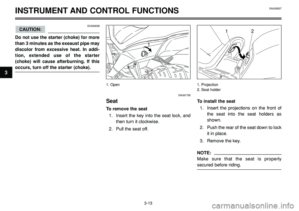
1. Open 1. Projection
2. Seat holder
To install the seat
1. Insert the projections on the front of
the seat into the seat holders as
shown.
2. Push the rear of the seat down to lock
it in place.
3. Remove the key.
NOTE:
Make sure that the seat is properly
secured before riding.
EAU00027
3-13
3
Page 71 of 96

2. Cowling
PERIODIC MAINTENANCE AND MINOR REPAIR
2
1
1
2
1
1
EAUB0013
Replacing the headlight and
auxiliary light bulb
This motorcycle is equipped with a quartz
bulb headlight. If the h")
1. Screw (x 2)
2. Cowling
PERIODIC MAINTENANCE AND MINOR REPAIR
2
1
1
2
1
1
EAUB0013
Replacing the headlight and
auxiliary light bulb
This motorcycle is equipped with a quartz
bulb headlight. If the headlight bulb or aux-
iliary light bulb burns out, replace it as fol-
lows.
NOTE:
Skip steps 6-10 if only the headlight bulb is
being replaced. Skip steps 2-5 if only the
auxiliary light bulb is being replaced.1. Remove the headlight by removing
the screws, then tilt the cowling for-
ward.
2. Disconnect the headlight coupler and
the auxiliary light leads, and then re-
move the headlight bulb cover.
3. Remove the headlight bulb holder by
turning it counterclockwise, and then
remove the defective bulb.
EW000119WARNING0
Headlight bulbs get very hot. There-
fore, keep flammable products away
from a lit headlight bulb, and do not
touch the bulb until it has cooled down.
4. Place a new bulb into position, and
then secure it with the bulb holder.
EAU00462
6-29
6
1. Headlight bulb cover
2. Auxiliary light bulb holder1. Headlight coupler
Page 72 of 96

PERIODIC MAINTENANCE AND MINOR REPAIR
1
1
2
EC000105
Do not touch the glass part of the head-
light bulb to keep it free from oil, other-
wise the transparency of the glass, the
luminosity of the bulb, and the bulb life
will be adversely affected.
Thoroughly clean off any dirt and fin-
gerprints on the headlight bulb using a
cloth moistened with alcohol or thin-
ner.
CAUTION:5. Install the headlight bulb cover, and
then connect the coupler and auxil-
iary light leads.
6. Remove the socket (together with the
bulb) by turning it counterclockwise.
7. Remove the defective bulb by push-
ing it in and turning it counterclock-
wise.
8. Insert a new bulb into the socket,
push it in, and then turn it clockwise
until it stops.
9. Install the socket (together with the
bulb) by turning it clockwise.10. Connect the auxiliary light bulb leads.
11. Tilt the cowling back to the original
position, and then install the headlight
by installing the screws.
EAU00462
6-30
6
1. Headlight bulb holder 1. Do not touch this area 1. Auxiliary light bulb holder
2. Auxiliary light bulb
Page 73 of 96

11
NOTE:
Before installing the headlight, be sure to
hook the headlight and auxiliary light bulb
lea")
EAU00462
1. Screw
2. Turn signal light len
PERIODIC MAINTENANCE AND MINOR REPAIR
1
2
1. Screw (x 2)
11
NOTE:
Before installing the headlight, be sure to
hook the headlight and auxiliary light bulb
leads into the guide to the left of the head-
light as shown.
12. Have a Yamaha dealer adjust the
headlight beam if necessary.
EAU03497
Replacing a turn signal light
bulb
1. Remove the turn signal light lens by
removing the screw.
2. Remove the defective bulb by push-
ing it in and turning it counterclock-
wise.
3. Insert a new bulb into the socket,
push it in, and then turn it clockwise
until it stops.
4. Install the lens by installing the screw.
EC000065
Do not overtighten the screw, other-
wise the lens may break.
CAUTION:
EAU01623
Replacing the tail/brake light
bulb
1. Remove the tail/brake light lens by re-
moving the screws.
2. Remove the defective bulb by push-
ing it in and turning it counterclock-
wise.
3. Insert a new bulb into the socket,
push it in, and then turn it clockwise
until it stops.
4. Install the lens by installing the
screws.
EC000108
Do not overtighten the screws, other-
wise the lens may break.
CAUTION:
6-31
6
1
1. Leads guide
.
2. Push the “RESET” button and hold it
down while turning the key")