Page 598 of 1690
141CN±01
A60622
A01045
A64005
A62837SST
14±96±
ENGINE MECHANICAL TIMING CHAIN OR BELT COVER OIL
SEAL(1ZZ±FE/3ZZ±FE)
AVENSIS REPAIR MANUAL (RM1018E)
TIMING GEAR COVER OIL SEAL(1ZZ±FE/3ZZ±FE)
REPLACEMENT
1.REMOVE FRONT WHEEL RH (See page 14±27)
2.REMOVE ENGINE UNDER COVER SUB±ASSY NO.1 (See page 14±27)
3.REMOVE ENGINE UNDER COVER RH (See page 14±27)
4.REMOVE RADIATOR SUPPORT OPENING COVER (See page 14±27)
5.REMOVE ENGINE ROOM COVER SIDE (See page 14±27) 6. REMOVE FAN AND GENERATOR V BELT
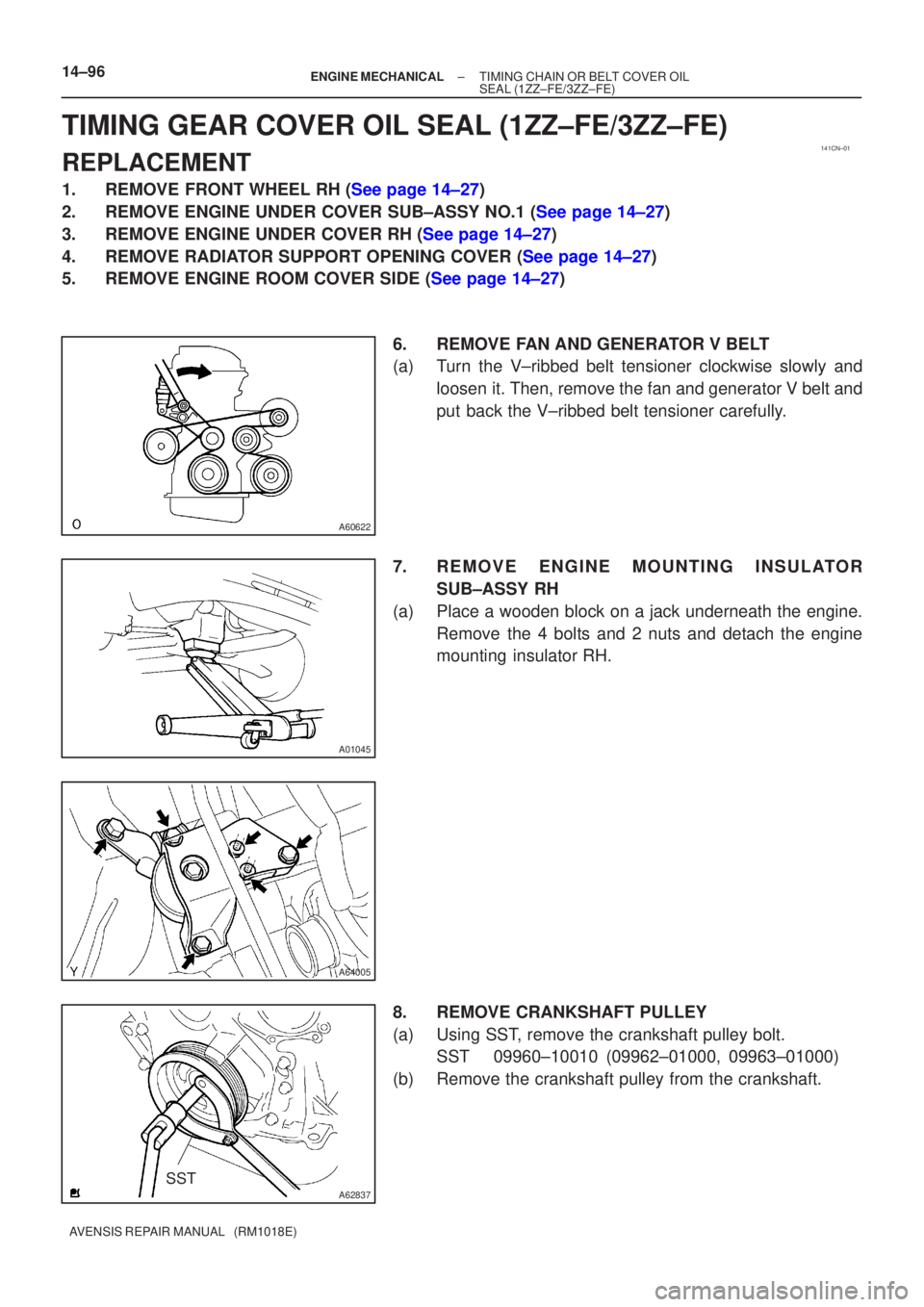
(a) Turn the V±ribbed belt tensioner clockwise slowly andloosen it. Then, remove the fan and generator V belt and
put back the V±ribbed belt tensioner carefully.
7. REMOVE ENGINE MOUNTING INSULATOR SUB±ASSY RH
(a) Place a wooden block on a jack underneath the engine. Remove the 4 bolts and 2 nuts and detach the engine
mounting insulator RH.
8. REMOVE CRANKSHAFT PULLEY
(a) Using SST, remove the crankshaft pulley bolt. SST 09960±10010 (09962±01000, 09963±01000)
(b) Remove the crankshaft pulley from the crankshaft.
Page 600 of 1690
141BH±01
A77281
A13697
SST
SST
A77381
SST
14±178
±
ENGINE MECHANICAL TIMING GEAR CASE OR TIMING CHAIN CASE OIL
SEAL(1AZ±FE)
AVENSIS REPAIR MANUAL (RM1018E)
TIMING GEAR CASE OR TIMING CHAIN CASE OIL
SEAL(1AZ±FE)
REPLACEMENT
1.REMOVE FRONT WHEEL RH
2.REMOVE RADIATOR SUPPORT OPENING COVER
3.REMOVE ENGINE ROOM COVER SIDE
4.REMOVE ENGINE UNDER COVER RH 5.REMOVE ENGINE COVER SUB±ASSY NO.1
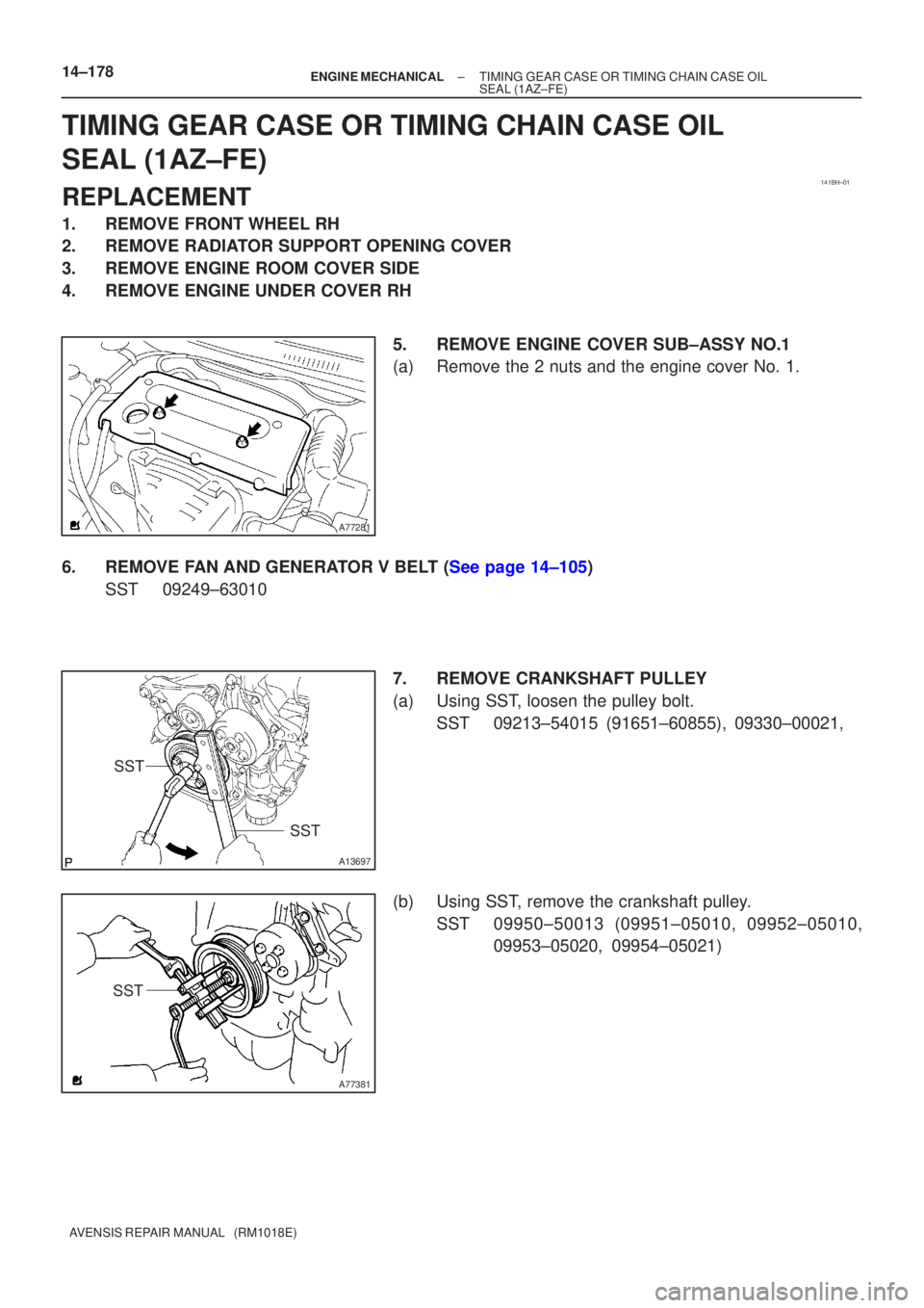
(a)Remove the 2 nuts and the engine cover No. 1.
6.REMOVE FAN AND GENERATOR V BELT (See page 14±105) SST 09249±63010
7. REMOVE CRANKSHAFT PULLEY
(a) Using SST, loosen the pulley bolt.SST 09213±54015 (91651±60855), 09330±00021,
(b) Using SST, remove the crankshaft pulley. SST 09950±50013 (09951±05010, 09952±05010, 09953±05020, 09954±05021)
Page 602 of 1690
141BR±01
A77339
A13697
SST
SST
A77381
SST
±
ENGINE MECHANICAL TIMING GEAR CASE OR TIMING CHAIN CASE OIL
SEAL(1AZ±FSE)14±263
AVENSIS REPAIR MANUAL (RM1018E)
TIMING GEAR CASE OR TIMING CHAIN CASE OIL
SEAL(1AZ±FSE)
REPLACEMENT
1.REMOVE FRONT WHEEL RH
2.REMOVE RADIATOR SUPPORT OPENING COVER
3.REMOVE ENGINE ROOM COVER SIDE
4.REMOVE ENGINE UNDER COVER RH
5.REMOVE ENGINE COVER SUB±ASSY NO.1
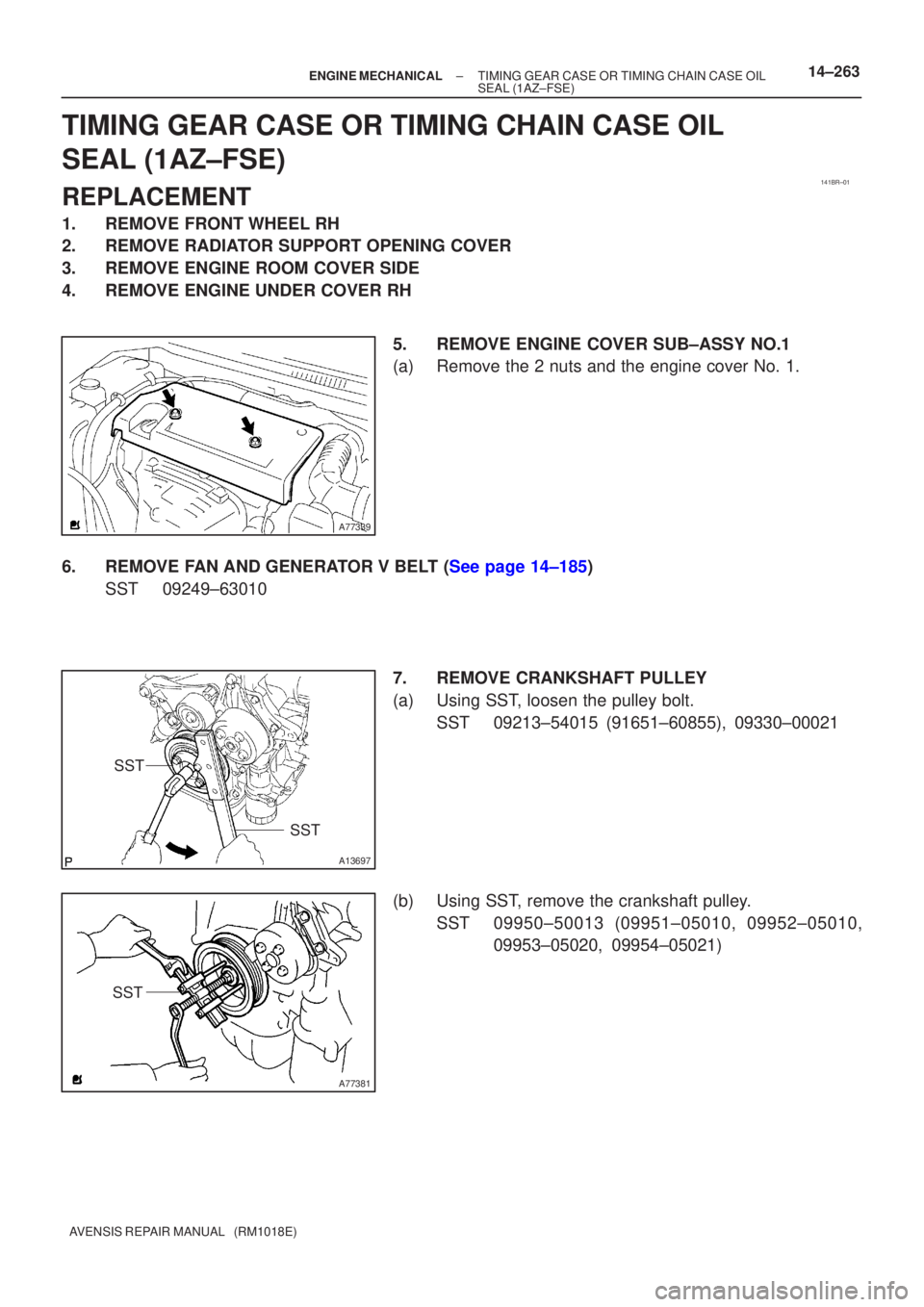
(a)Remove the 2 nuts and the engine cover No. 1.
6.REMOVE FAN AND GENERATOR V BELT (See page 14±185) SST 09249±63010
7. REMOVE CRANKSHAFT PULLEY
(a) Using SST, loosen the pulley bolt.SST 09213±54015 (91651±60855), 09330±00021
(b) Using SST, remove the crankshaft pulley. SST 09950±50013 (09951±05010, 09952±05010, 09953±05020, 09954±05021)
Page 604 of 1690
141B6±01
A77281
A77378
No. 1 Cylinder TDC/Compression
IN
EX
A77379
No. 4 Cylinder TDC/Compression
IN
EX
14±106
±
ENGINE MECHANICAL VALVE CLEARANCE(1AZ±FE)
AVENSIS REPAIR MANUAL (RM1018E)
VALVE CLEARANCE(1AZ±FE)
ADJUSTMENT
1.REMOVE RADIATOR SUPPORT OPENING COVER
2.REMOVE ENGINE ROOM COVER SIDE
3.REMOVE ENGINE UNDER COVER RH 4.REMOVE ENGINE COVER SUB±ASSY NO.1
(a)Remove 2 nuts and the engine cover No. 1.
5.REMOVE IGNITION COIL ASSY
(a)Remove 4 bolts and the ignition coils.
6.REMOVE CYLINDER HEAD COVER SUB±ASSY (See page 14±171)
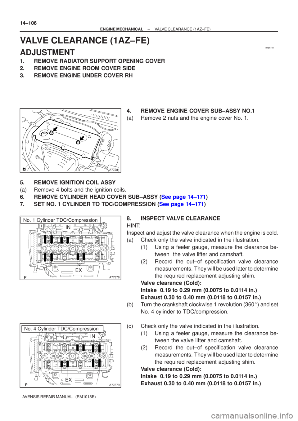
7.SET NO. 1 CYLINDER TO TDC/COMPRESSION (See page 14±171) 8. INSPECT VALVE CLEARANCE
HINT:
Inspect and adjust the valve clearance when the engine is cold.
(a) Check only the valve indicated in the illustration.(1) Using a feeler gauge, measure the clearance be-tween the valve lifter and camshaft.
(2) Record the out±of specification valve clearance measurements. They will be used later to determine
the required replacement adjusting shim.
Valve clearance (Cold):
Intake 0.19 to 0.29 mm (0.0075 to 0.0114 in.)
Exhaust 0.30 to 0.40 mm (0.0118 to 0.0157 in.)
(b) Turn the crankshaft clockwise 1 revolution (360 �) and set
No. 4 cylinder to TDC/compression.
(c) Check only the valve indicated in the illustration. (1) Using a feeler gauge, measure the clearance be-tween the valve lifter and camshaft.
(2) Record the out±of specification valve clearance measurements. They will be used later to determine
the required replacement adjusting shim.
Valve clearance (Cold):
Intake 0.19 to 0.29 mm (0.0075 to 0.0114 in.)
Exhaust 0.30 to 0.40 mm (0.0118 to 0.0157 in.)
Page 610 of 1690
A64058
A64856
A62185
Mark
Mark
Mark
Timing Chain
Cover Surface
Timing
Notch
A01131
± ENGINE MECHANICALVALVE CLEARANCE (1ZZ±FE/3ZZ±FE)
14±7
AVENSIS REPAIR MANUAL (RM1018E)
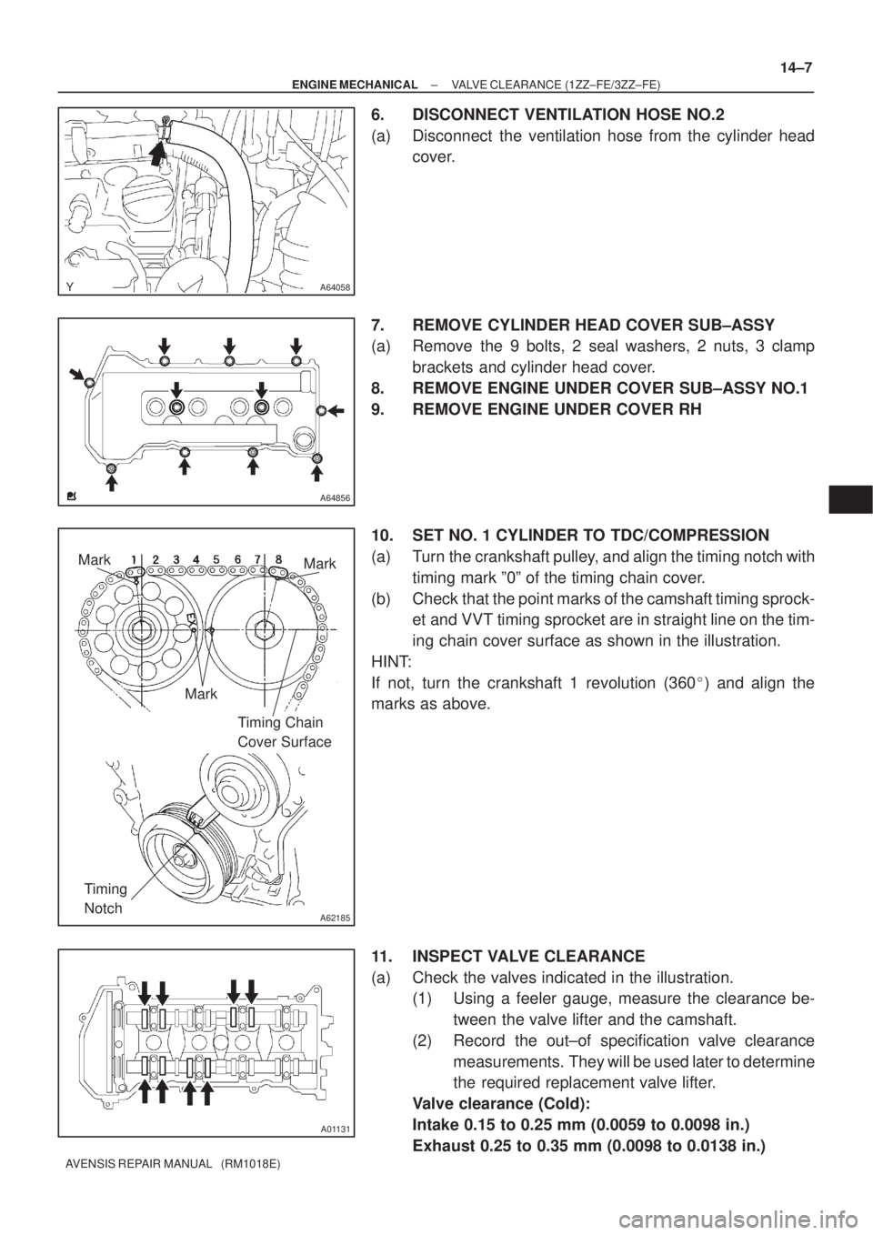
6. DISCONNECT VENTILATION HOSE NO.2
(a) Disconnect the ventilation hose from the cylinder head
cover.
7. REMOVE CYLINDER HEAD COVER SUB±ASSY
(a) Remove the 9 bolts, 2 seal washers, 2 nuts, 3 clamp
brackets and cylinder head cover.
8. REMOVE ENGINE UNDER COVER SUB±ASSY NO.1
9. REMOVE ENGINE UNDER COVER RH
10. SET NO. 1 CYLINDER TO TDC/COMPRESSION
(a) Turn the crankshaft pulley, and align the timing notch with
timing mark º0º of the timing chain cover.
(b) Check that the point marks of the camshaft timing sprock-
et and VVT timing sprocket are in straight line on the tim-
ing chain cover surface as shown in the illustration.
HINT:
If not, turn the crankshaft 1 revolution (360�) and align the
marks as above.
11. INSPECT VALVE CLEARANCE
(a) Check the valves indicated in the illustration.
(1) Using a feeler gauge, measure the clearance be-
tween the valve lifter and the camshaft.
(2) Record the out±of specification valve clearance
measurements. They will be used later to determine
the required replacement valve lifter.
Valve clearance (Cold):
Intake 0.15 to 0.25 mm (0.0059 to 0.0098 in.)
Exhaust 0.25 to 0.35 mm (0.0098 to 0.0138 in.)
Page 638 of 1690
760WY±01
B67425
Claw
B67431
± EXTERIOR/INTERIOR TRIMFRONT BUMPER
76±3
AVENSIS REPAIR MANUAL (RM1018E)
REPLACEMENT
HINT:
The installation is in the reverse order of the removal. However, when there is a special point concerning
the installation, it is indicated.
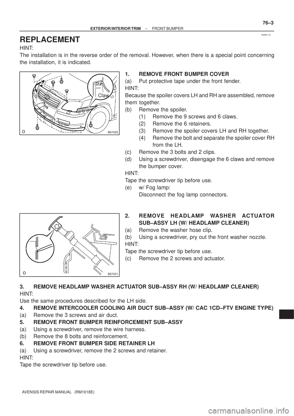
1. REMOVE FRONT BUMPER COVER
(a) Put protective tape under the front fender.
HINT:
Because the spoiler covers LH and RH are assembled, remove
them together.
(b) Remove the spoiler.
(1) Remove the 9 screws and 6 claws.
(2) Remove the 6 retainers.
(3) Remove the spoiler covers LH and RH together.
(4) Remove the bolt and separate the spoiler cover RH
from the LH.
(c) Remove the 3 bolts and 2 clips.
(d) Using a screwdriver, disengage the 6 claws and remove
the bumper cover.
HINT:
Tape the screwdriver tip before use.
(e) w/ Fog lamp:
Disconnect the fog lamp connectors.
2. R E M O V E H E A D L A M P WA S H E R A C T U ATO R
SUB±ASSY LH (W/ HEADLAMP CLEANER)
(a) Remove the washer hose clip.
(b) Using a screwdriver, pry out the front washer nozzle.
HINT:
Tape the screwdriver tip before use.
(c) Remove the 2 screws and actuator.
3. REMOVE HEADLAMP WASHER ACTUATOR SUB±ASSY RH (W/ HEADLAMP CLEANER)
HINT:
Use the same procedures described for the LH side.
4. REMOVE INTERCOOLER COOLING AIR DUCT SUB±ASSY (W/ CAC 1CD±FTV ENGINE TYPE)
(a) Remove the 3 screws and air duct.
5. REMOVE FRONT BUMPER REINFORCEMENT SUB±ASSY
(a) Using a screwdriver, remove the wire harness.
(b) Remove the 8 bolts and reinforcement.
6. REMOVE FRONT BUMPER SIDE RETAINER LH
(a) Using a screwdriver, remove the 2 screws and retainer.
HINT:
Tape the screwdriver tip before use.
Page 727 of 1690
A79149
30 cm
(11.81 in.)
SST
±
FUEL COMMON RAIL ASSY(1CD±FTV)
11±81
AVENSIS REPAIR MANUAL (RM1018E)
19.INSTALL FUEL INLET PIPE SUB±ASSY
NOTICE:
�In case of having the common rail replaced, must re-
place fuel inlet pipe, too.
�When assembling the pipe, perform the operation
with the engine cold under room temperature.
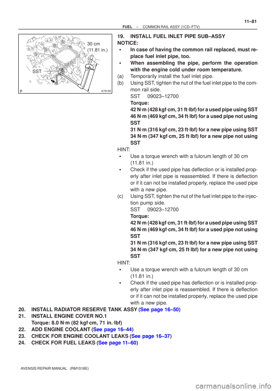
(a)Temporarily install the fuel inlet pipe.
(b)Using SST, tighten the nut of the fuel inlet pipe to the com-
mon rail side.
SST09023±12700
Torque:
42 N�m (428 kgf �cm, 31 ft �lbf) for a used pipe using SST
46 N �m (469 kgf �cm, 34 ft �lbf) for a used pipe not using
SST
31 N �m (316 kgf �cm, 23 ft �lbf) for a new pipe using SST
34 N �m (347 kgf �cm, 25 ft �lbf) for a new pipe not using
SST
HINT:
�Use a torque wrench with a fulcrum length of 30 cm
(11.81 in.)
�Check if the used pipe has deflection or is installed prop-
erly after inlet pipe is reassembled. If there is deflection
or if it can not be installed properly, replace the used pipe
with a new pipe.
(c)Using SST, tighten the nut of the fuel inlet pipe to the injec-
tion pump side.
SST09023±12700
Torque:
42 N�m (428 kgf �cm, 31 ft �lbf) for a used pipe using SST
46 N �m (469 kgf �cm, 34 ft �lbf) for a used pipe not using
SST
31 N �m (316 kgf �cm, 23 ft �lbf) for a new pipe using SST
34 N �m (347 kgf �cm, 25 ft �lbf) for a new pipe not using
SST
HINT:
�Use a torque wrench with a fulcrum length of 30 cm
(11.81 in.)
�Check if the used pipe has deflection or is installed prop-
erly after inlet pipe is reassembled. If there is deflection
or if it can not be installed properly, replace the used pipe
with a new pipe.
20.INSTALL RADIATOR RESERVE TANK ASSY(See page 16±50)
21. INSTALL ENGINE COVER NO.1 Torque: 8.0 N �m (82 kgf �cm, 71 in. �lbf)
22.ADD ENGINE COOLANT(See page 16±44)
23.CHECK FOR ENGINE COOLANT LEAKS(See page 16±37)
24.CHECK FOR FUEL LEAKS(See page 11±60)
Page 763 of 1690
110UW±01
A75341
Fuel
Pump
Connector
B00679
Vinyl or Plastic Bag
±
FUEL FUEL SYSTEM(1AZ±FE)
11±15
AVENSIS REPAIR MANUAL (RM1018E)
FUEL SYSTEM(1AZ±FE)
PRECAUTION
1.PRECAUTION
(a)Before working on fuel system, disconnect negative (±) battery cable.
(b)Do not smoke or work near fire when handling the fuel system.
(c)Keep gasoline away from rubber or leather parts.
2.DISCHARGE FUEL SYSTEM PRESSURE
CAUTION:
�Do not disconnect any part of the fuel system until
you have discharged the fuel system pressure.
�Even after discharging the fuel pressure, place a
shop rag over fittings as you separate them to reduce
risk of fuel spray on yourself or in the engine compart-
ment.
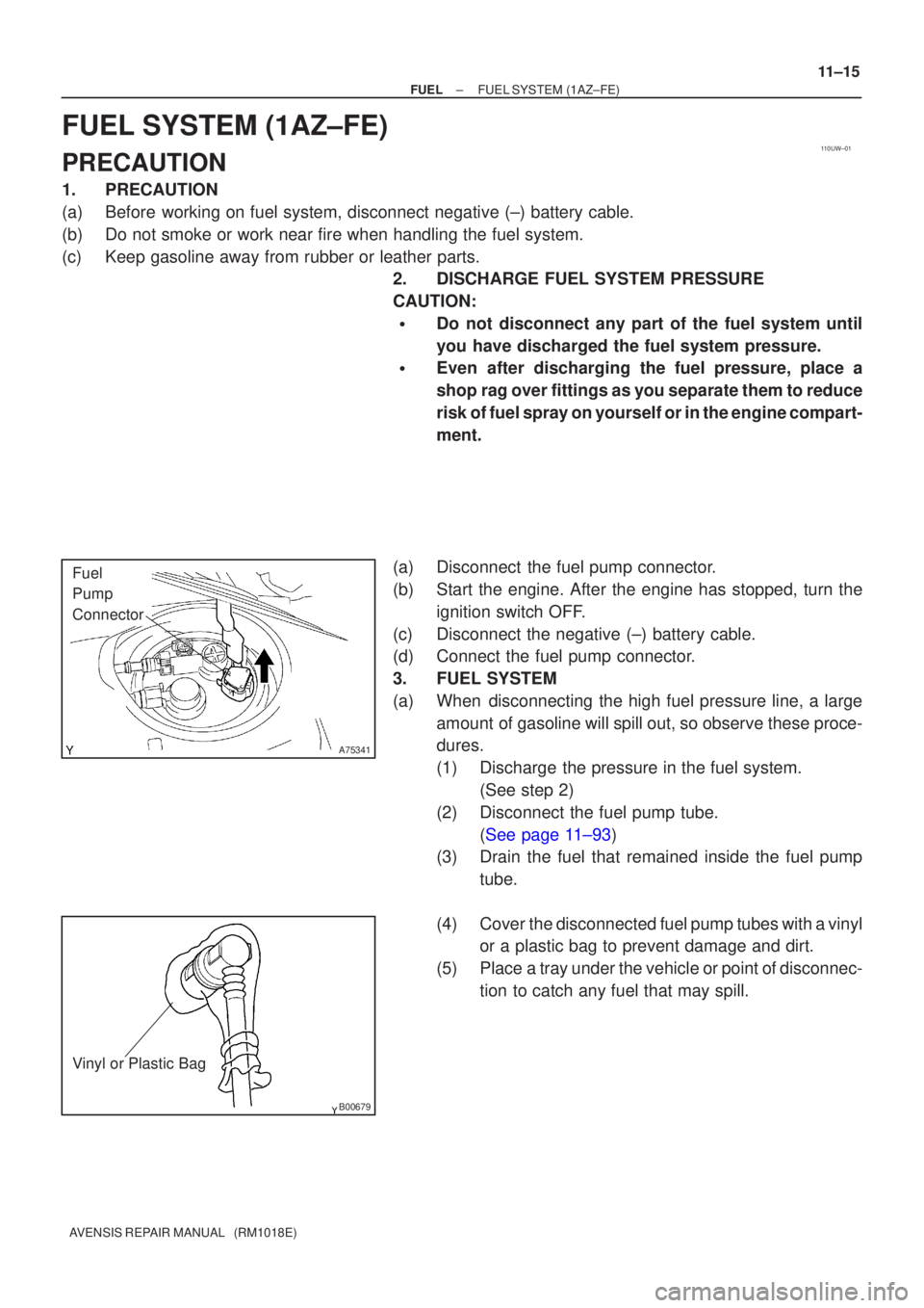
(a)Disconnect the fuel pump connector.
(b)Start the engine. After the engine has stopped, turn the ignition switch OFF.
(c)Disconnect the negative (±) battery cable.
(d)Connect the fuel pump connector.
3.FUEL SYSTEM
(a)When disconnecting the high fuel pressure line, a large amount of gasoline will spill out, so observe these proce-
dures.
(1)Discharge the pressure in the fuel system. (See step 2)
(2)Disconnect the fuel pump tube. (See page 11±93)
(3) Drain the fuel that remained inside the fuel pump
tube.
(4) Cover the disconnected fuel pump tubes with a vinyl or a plastic bag to prevent damage and dirt.
(5) Place a tray under the vehicle or point of disconnec- tion to catch any fuel that may spill.