Page 569 of 1690
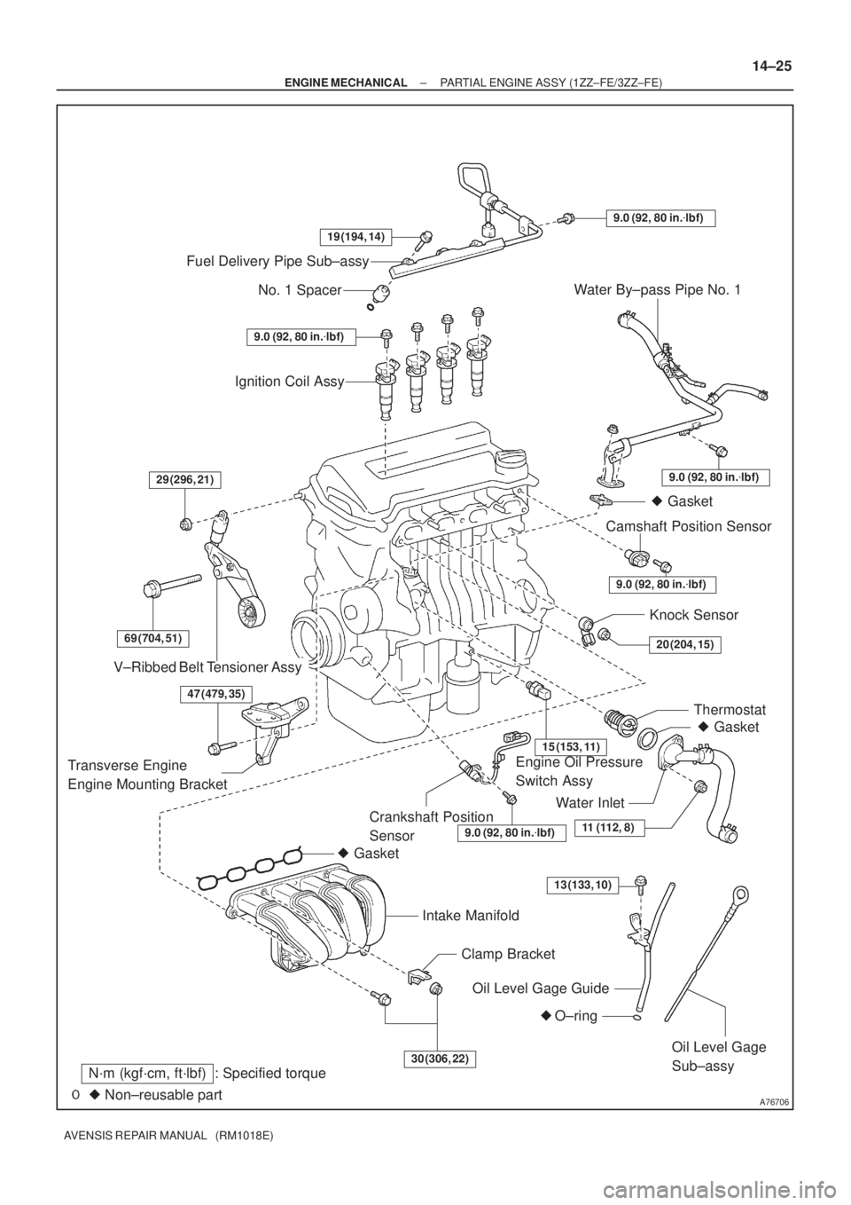
A76706
Fuel Delivery Pipe Sub±assy
No. 1 Spacer
Ignition Coil Assy
V±Ribbed Belt Tensioner Assy
� Gasket
Intake Manifold
Clamp Bracket
Oil Level Gage Guide
� O±ring
Oil Level Gage
Sub±assy
Crankshaft Position
Sensor� Gasket Thermostat Knock Sensor
Engine Oil Pressure
Switch AssyCamshaft Position Sensor� Gasket Water By±pass Pipe No. 1
� Non±reusable part
N´m (kgf´cm, ft´lbf) : Specified torque
Water Inlet
19 (194, 14)
9.0 (92, 80 in.�lbf)
9.0 (92, 80 in.�lbf)
9.0 (92, 80 in.�lbf)
9.0 (92, 80 in.�lbf)29 (296, 21)
69 (704, 51)
15 (153, 11)
20 (204, 15)
11 (112, 8)
30 (306, 22)
9.0 (92, 80 in.�lbf)
Transverse Engine
Engine Mounting Bracket
13 (133, 10)
47 (479, 35)
± ENGINE MECHANICALPARTIAL ENGINE ASSY (1ZZ±FE/3ZZ±FE)
14±25
AVENSIS REPAIR MANUAL (RM1018E)
Page 571 of 1690
141CG±01
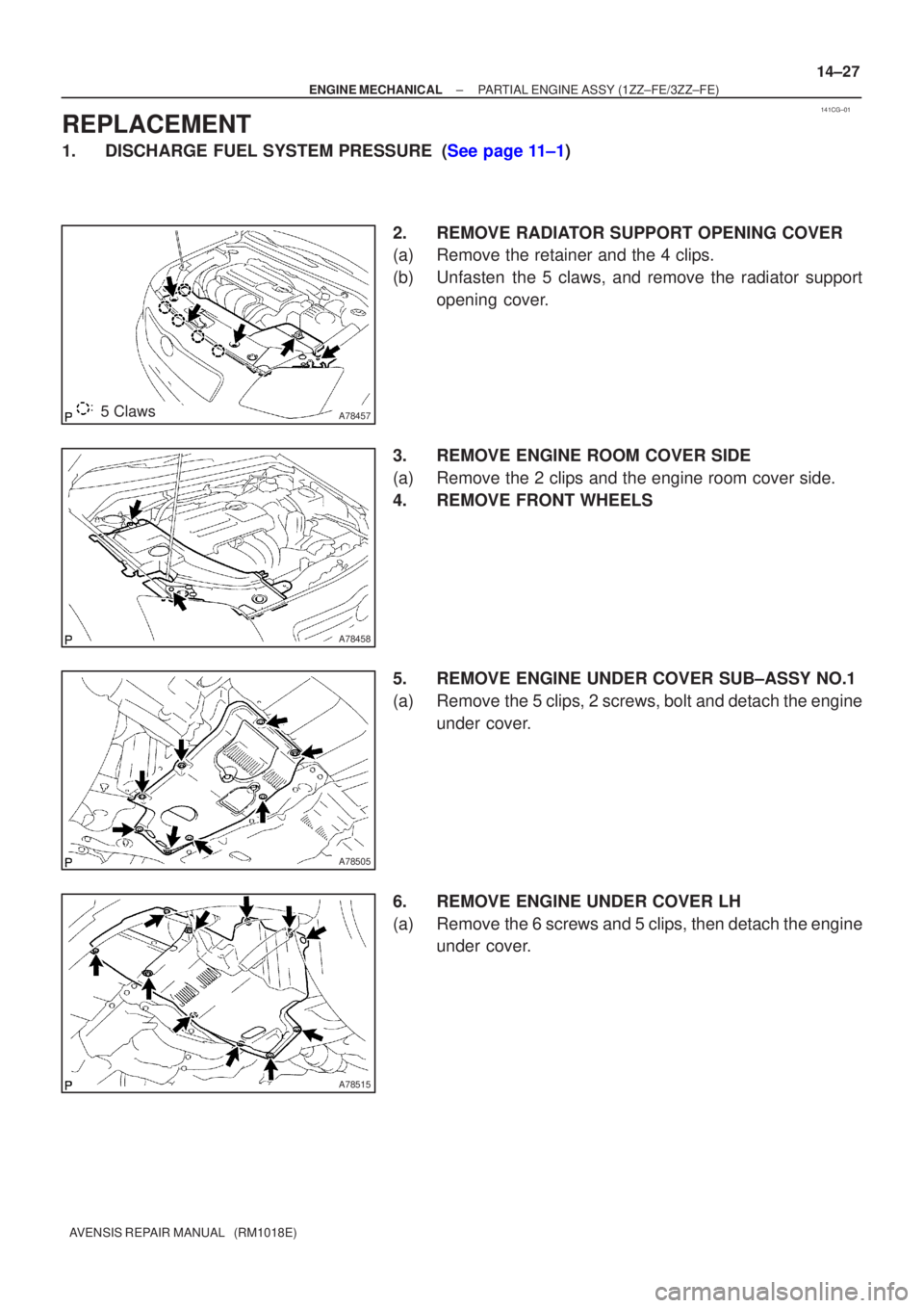
A784575 Claws
A78458
A78505
A78515
±
ENGINE MECHANICAL PARTIAL ENGINE ASSY (1ZZ±FE/3ZZ±FE)
14±27
AVENSIS REPAIR MANUAL (RM1018E)
REPLACEMENT
1.DISCHARGE FUEL SYSTEM PRESSURE (See page 11±1)
2. REMOVE RADIATOR SUPPORT OPENING COVER
(a) Remove the retainer and the 4 clips.
(b) Unfasten the 5 claws, and remove the radiator supportopening cover.
3. REMOVE ENGINE ROOM COVER SIDE
(a) Remove the 2 clips and the engine room cover side.
4. REMOVE FRONT WHEELS
5. REMOVE ENGINE UNDER COVER SUB±ASSY NO.1
(a) Remove the 5 clips, 2 screws, bolt and detach the engine under cover.
6. REMOVE ENGINE UNDER COVER LH
(a) Remove the 6 screws and 5 clips, then detach the engine under cover.
Page 732 of 1690
110U1±01
A77908
Retainer
(at 4 places)
Insert
SST
Turn
Fuel Pipe
Clamp
A76220
O±ring
Nylon Tube HousingPipe
Retainer
A77909
11±26
±
FUEL FUEL INJECTOR ASSY(1AZ±FE)
AVENSIS REPAIR MANUAL (RM1018E)
REPLACEMENT
1.DISCHARGE FUEL SYSTEM PRESSURE (See page 11±15)
2.REMOVE ENGINE COVER SUB±ASSY NO.1 (See page 10±26)
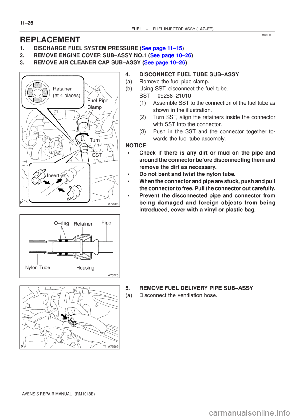
3.REMOVE AIR CLEANER CAP SUB±ASSY (See page 10±26) 4. DISCONNECT FUEL TUBE SUB±ASSY
(a) Remove the fuel pipe clamp.
(b) Using SST, disconnect the fuel tube.SST 09268±21010
(1) Assemble SST to the connection of the fuel tube asshown in the illustration.
(2) Turn SST, align the retainers inside the connector
with SST into the connector.
(3) Push in the SST and the connector together to- wards the fuel tube assembly.
NOTICE:
�Check if there is any dirt or mud on the pipe and
around the connector before disconnecting them and
remove the dirt as necessary.
�Do not bent and twist the nylon tube.
�When the connector and pipe are stuck, push and pull
the connector to free. Pull the connector out carefully.
�Prevent the disconnected pipe and connector from
being damaged and foreign objects from being
introduced, cover with a vinyl or plastic bag.
5. REMOVE FUEL DELIVERY PIPE SUB±ASSY
(a) Disconnect the ventilation hose.
Page 737 of 1690
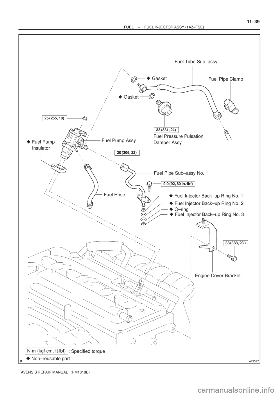
A79577
N´m (kgf´cm, ft´lbf)
: Specified torque
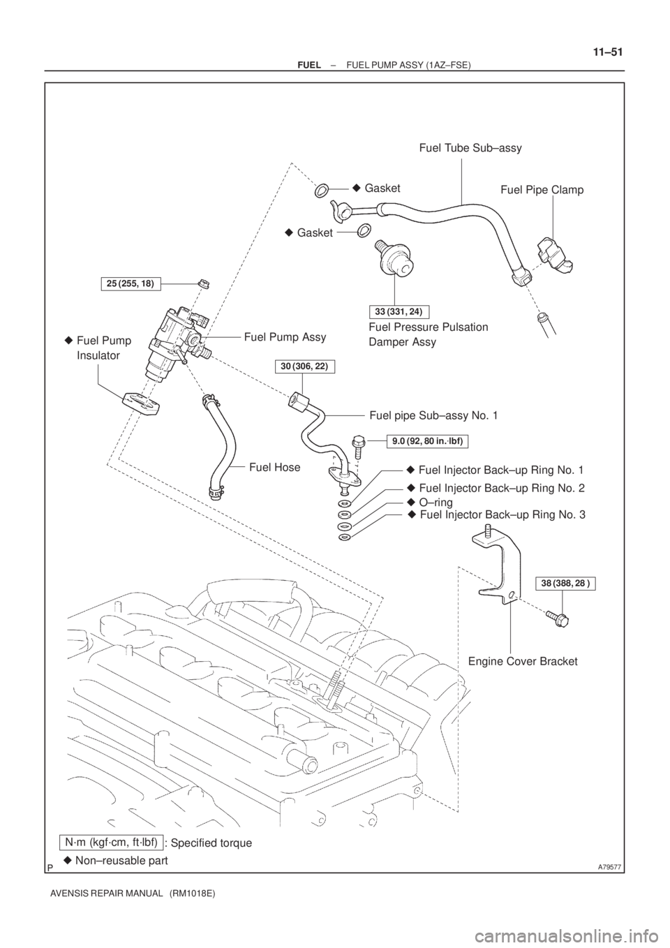
� Non±reusable part� Gasket� GasketFuel Tube Sub±assy
Fuel Pipe Clamp
Fuel Pressure Pulsation
Damper Assy Fuel Pump Assy
� Fuel Pump
Insulator
Fuel HoseFuel Pipe Sub±assy No. 1
� Fuel Injector Back±up Ring No. 1
25 (255, 18)
33 (331, 24)
9.0 (92, 80 in.�lbf)
38 (388, 28 )
30 (306, 22)
� Fuel Injector Back±up Ring No. 2
� Fuel Injector Back±up Ring No. 3 � O±ring
Engine Cover Bracket
± FUELFUEL INJECTOR ASSY (1AZ±FSE)
11±39
AVENSIS REPAIR MANUAL (RM1018E)
Page 741 of 1690
110TZ±01
A78471
Retainer
(at 4 places)
Insert
SST
Turn
Fuel Pipe
Clamp
A76220
O±ring
Nylon Tube HousingPipe
Retainer
A78472
±
FUEL FUEL INJECTOR ASSY(1ZZ±FE/3ZZ±FE)
11±11
AVENSIS REPAIR MANUAL (RM1018E)
REPLACEMENT
1.DISCHARGE FUEL SYSTEM PRESSURE (See page 11±1)
2.REMOVE CYLINDER HEAD COVER NO.2 (See page 10±9)
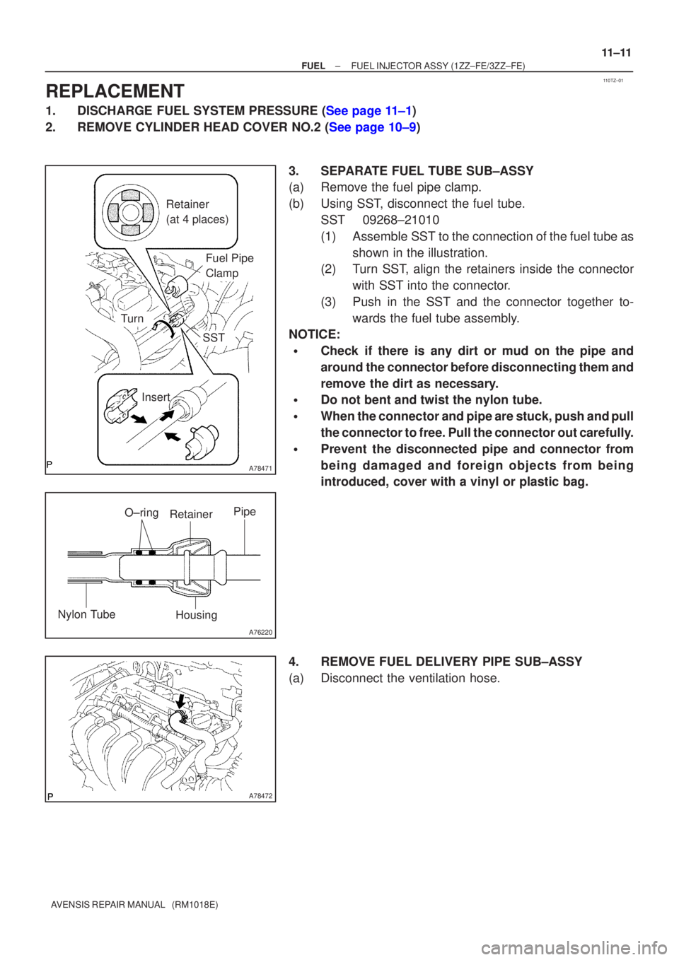
3. SEPARATE FUEL TUBE SUB±ASSY
(a) Remove the fuel pipe clamp.
(b) Using SST, disconnect the fuel tube.SST 09268±21010
(1) Assemble SST to the connection of the fuel tube asshown in the illustration.
(2) Turn SST, align the retainers inside the connector
with SST into the connector.
(3) Push in the SST and the connector together to- wards the fuel tube assembly.
NOTICE:
�Check if there is any dirt or mud on the pipe and
around the connector before disconnecting them and
remove the dirt as necessary.
�Do not bent and twist the nylon tube.
�When the connector and pipe are stuck, push and pull
the connector to free. Pull the connector out carefully.
�Prevent the disconnected pipe and connector from
being damaged and foreign objects from being
introduced, cover with a vinyl or plastic bag.
4. REMOVE FUEL DELIVERY PIPE SUB±ASSY
(a) Disconnect the ventilation hose.
Page 745 of 1690
110U2±01
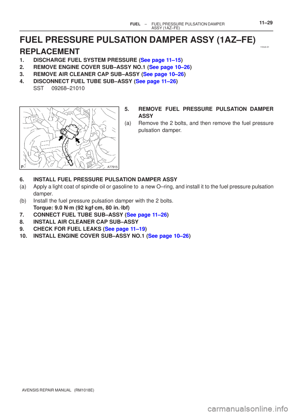
A77915
±
FUEL FUEL PRESSURE PULSATION DAMPER
ASSY(1AZ±FE)11±29
AVENSIS REPAIR MANUAL (RM1018E)
FUEL PRESSURE PULSATION DAMPER ASSY(1AZ±FE)
REPLACEMENT
1.DISCHARGE FUEL SYSTEM PRESSURE (See page 11±15)
2.REMOVE ENGINE COVER SUB±ASSY NO.1 (See page 10±26)
3.REMOVE AIR CLEANER CAP SUB±ASSY (See page 10±26)
4.DISCONNECT FUEL TUBE SUB±ASSY (See page 11±26)
SST09268±21010
5.REMOVE FUEL PRESSURE PULSATION DAMPERASSY
(a)Remove the 2 bolts, and then remove the fuel pressure pulsation damper.
6.INSTALL FUEL PRESSURE PULSATION DAMPER ASSY
(a)Apply a light coat of spindle oil or gasoline to a new O±ring, and instal\
l it to the fuel pressure pulsation damper.
(b)Install the fuel pressure pulsation damper with the 2 bolts. Torque: 9.0 N �m (92 kgf �cm, 80 in. �lbf)
7.CONNECT FUEL TUBE SUB±ASSY (See page 11±26)
8. INSTALL AIR CLEANER CAP SUB±ASSY
9.CHECK FOR FUEL LEAKS (See page 11±19)
10.INSTALL ENGINE COVER SUB±ASSY NO.1 (See page 10±26)
Page 748 of 1690
A79577
N´m (kgf´cm, ft´lbf)
: Specified torque
� Non±reusable part� Gasket� GasketFuel Tube Sub±assy
Fuel Pipe Clamp
Fuel Pressure Pulsation
Damper Assy Fuel Pump Assy
� Fuel Pump
Insulator
Fuel HoseFuel pipe Sub±assy No. 1
� Fuel Injector Back±up Ring No. 1
25 (255, 18)
33 (331, 24)
9.0 (92, 80 in.�lbf)
38 (388, 28 )
30 (306, 22)
� Fuel Injector Back±up Ring No. 2
� Fuel Injector Back±up Ring No. 3 � O±ring
Engine Cover Bracket
± FUELFUEL PUMP ASSY (1AZ±FSE)
11±51
AVENSIS REPAIR MANUAL (RM1018E)
Page 749 of 1690
110TB±01
A79569
A79570
SST
A79571
A79572
11±52
±
FUEL FUEL PUMP ASSY(1AZ±FSE)
AVENSIS REPAIR MANUAL (RM1018E)
REPLACEMENT
1.DISCHARGE FUEL SYSTEM PRESSURE (See page 11±30)
2.REMOVE RADIATOR SUPPORT OPENING COVER (See page 18±16)
3.REMOVE ENGINE COVER SUB±ASSY NO.1 (See page 10±44)
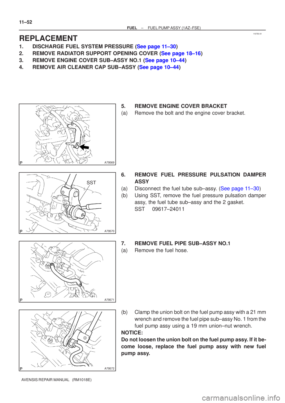
4.REMOVE AIR CLEANER CAP SUB±ASSY (See page 10±44) 5.REMOVE ENGINE COVER BRACKET
(a)Remove the bolt and the engine cover bracket.
6.REMOVE FUEL PRESSURE PULSATION DAMPERASSY
(a)Disconnect the fuel tube sub±assy. (See page 11±30)
(b) Using SST, remove the fuel pressure pulsation damper assy, the fuel tube sub±assy and the 2 gasket.
SST 09617±24011
7. REMOVE FUEL PIPE SUB±ASSY NO.1
(a) Remove the fuel hose.
(b) Clamp the union bolt on the fuel pump assy with a 21 mm wrench and remove the fuel pipe sub±assy No. 1 from the
fuel pump assy using a 19 mm union±nut wrench.
NOTICE:
Do not loosen the union bolt on the fuel pump assy. If it be-
come loose, replace the fuel pump assy with new fuel
pump assy.