Page 1092 of 1690
410DU±01
D30480
D30081
41±24
±
MANUAL TRANSMISSION/TRANSAXLE MANUAL TRANSAXLE ASSY (1AZ±FE/1AZ±FSE)
AVENSIS REPAIR MANUAL (RM1018E)
REPLACEMENT
1. INSPECT CENTER FRONT WHEEL
2.REMOVE COLUMN HOLE COVER SILENCER SHEET (See page 50±9)
3.SEPARATE STEERING INTERMEDIATE SHAFT ASSY NO.2 (See page 50±9)
4.REMOVE STEERING COLUMN HOLE COVER SUB±ASSY NO.1 (See page 50±9)
5.REMOVE STEERING INTERMEDIATE SHAFT (See page 50±9)
6. REMOVE FRONT WHEELS
7. REMOVE ENGINE UNDER COVER LH
8. REMOVE ENGINE UNDER COVER RH
9. DRAIN TRANSAXLE OIL Torque: 49 N �m (500 kgf �cm, 36 ft �lbf)
10. REMOVE HOOD SUB±ASSY
11. REMOVE RADIATOR SUPPORT OPENING COVER
12. REMOVE ENGINE ROOM COVER SIDE
13. REMOVE ENGINE COVER SUB±ASSY NO.1
14. REMOVE AIR CLEANER ASSY
15. REMOVE BATTERY CLAMP SUB±ASSY
16. REMOVE BATTERY
17. REMOVE BATTERY TRAY
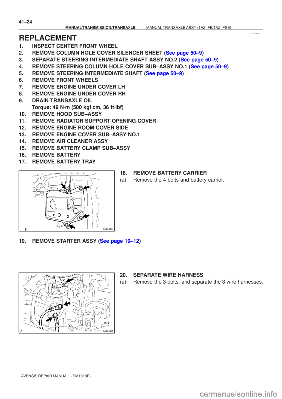
18. REMOVE BATTERY CARRIER
(a) Remove the 4 bolts and battery carrier.
19.REMOVE STARTER ASSY (See page 19±12) 20. SEPARATE WIRE HARNESS
(a) Remove the 3 bolts, and separate the 3 wire harnesses.
Page 1101 of 1690
410DY±01
D26902
D26903
±
MANUAL TRANSMISSION/TRANSAXLE MANUAL TRANSAXLE ASSY (1CD±FTV)
41±33
AVENSIS REPAIR MANUAL (RM1018E)
REPLACEMENT
1. INSPECT CENTER FRONT WHEEL
2.REMOVE COLUMN HOLE COVER SILENCER SHEET (See page 50±9)
3.SEPARATE STEERING INTERMEDIATE SHAFT ASSY NO.2 (See page 50±9)
4.REMOVE STEERING COLUMN HOLE COVER SUB±ASSY NO.1 (See page 50±9)
5.REMOVE STEERING INTERMEDIATE SHAFT (See page 50±9)
6. REMOVE FRONT WHEELS
7. REMOVE ENGINE UNDER COVER RH
8. REMOVE ENGINE UNDER COVER LH
9. DRAIN TRANSAXLE OIL
Torque: 49 N �m (500 kgf �cm, 36 ft �lbf)
10. REMOVE HOOD SUB±ASSY
11. REMOVE RADIATOR SUPPORT OPENING COVER
12. REMOVE ENGINE ROOM COVER SIDE
13. REMOVE ENGINE COVER NO.1
14. REMOVE AIR CLEANER ASSY
15. REMOVE BATTERY CLAMP SUB±ASSY
16. REMOVE BATTERY
17. REMOVE BATTERY TRAY
18.REMOVE AIR TUBE NO.1 (See page 14±286)
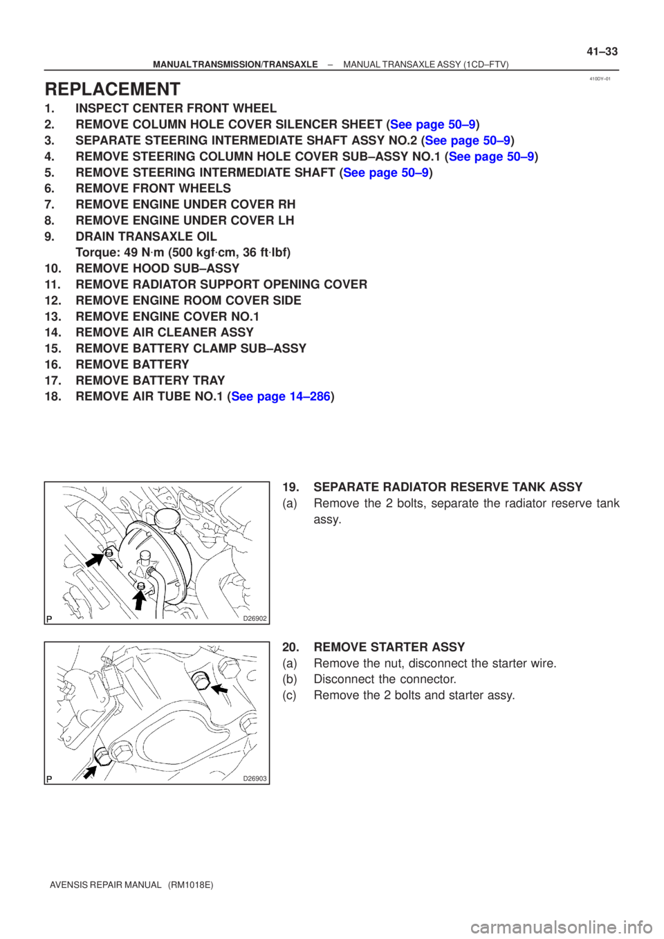
19. SEPARATE RADIATOR RESERVE TANK ASSY
(a) Remove the 2 bolts, separate the radiator reserve tankassy.
20. REMOVE STARTER ASSY
(a) Remove the nut, disconnect the starter wire.
(b) Disconnect the connector.
(c) Remove the 2 bolts and starter assy.
Page 1314 of 1690
610CN±02
B65506
±
SEAT BELT FRONT SEAT BELT
61±7
AVENSIS REPAIR MANUAL (RM1018E)
REPLACEMENT
HINT:
�The installation is in the reverse order of the removal. However, when there is a special point concern-
ing the installation, it is indicated.
�Use the same procedures on the LH side as on the RH side.
1. DISCONNECT BATTERY NEGATIVE TERMINAL
2. REMOVE FRONT SEAT ASSEMBLY RH
3. REMOVE FRONT SEAT INNER BELT ASSY RH
4.REMOVE FRONT DOOR SCUFF PLATE RH (See page 76±36, 76±45, 76±54)
5.REMOVE REAR DOOR SCUFF PLATE RH (See page 76±36, 76±45, 76±54)
6. REMOVE FRONT DOOR WEATHERSTRIP RH
7. REMOVE REAR DOOR WEATHERSTRIP RH
8.REMOVE CENTER PILLAR GARNISH LOWER RH (See page 76±36, 76±45, 76±54)
9.REMOVE CENTER PILLAR GARNISH UPPER RH (See page 76±36, 76±45, 76±54) 10. REMOVE FRONT SEAT OUTER BELT ASSY RH
NOTICE:
�Removal operation concerning the seat belt with the
pretensioner must be started when 90 seconds or
more time has passed after the ignition switch is
turned OFF and the battery negative terminal is dis-
connected.
�Carefully read the notices for the ºpretensionerº in
the SRS airbag system section and the front seat out-
er belt assy section.
(a) Remove the nut and the outer belt on the shoulder anchor
side.
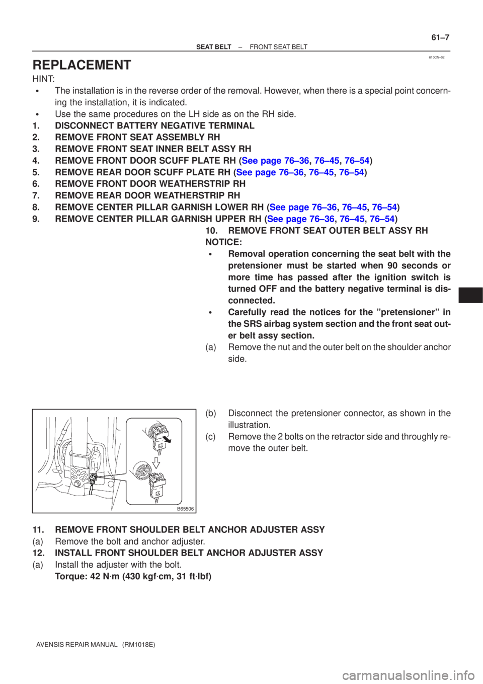
(b) Disconnect the pretensioner connector, as shown in the illustration.
(c) Remove the 2 bolts on the retractor side and throughly re- move the outer belt.
11. REMOVE FRONT SHOULDER BELT ANCHOR ADJUSTER ASSY
(a) Remove the bolt and anchor adjuster.
12. INSTALL FRONT SHOULDER BELT ANCHOR ADJUSTER ASSY
(a) Install the adjuster with the bolt. Torque: 42 N �m (430 kgf �cm, 31 ft �lbf)
Page 1449 of 1690
190NJ±01
A77898
A77899
(a)
(a)
(a)(c)
(d)
Terminal Cap Cover
A77900
A77901
19±12
±
STARTING & CHARGING STARTER ASSY(1AZ±FE/1AZ±FSE)
AVENSIS REPAIR MANUAL (RM1018E)
STARTER ASSY(1AZ±FE/1AZ±FSE)
REPLACEMENT
1.REMOVE RADIATOR SUPPORT OPENING COVER (See page 10±26)
2. REMOVE BATTERY CLAMP SUB±ASSY
3. REMOVE BATTERY
4. REMOVE BATTERY TRAY 5. REMOVE BATTERY CARRIER
(a) Remove the 4 bolts, and then remove the battery carrier.
6. REMOVE STARTER ASSY
(a) Remove the 3 wire harness clamps.
(b) Open the terminal cap cover.
(c) Remove the nut and disconnect the starter wire.
(d) Disconnect the starter connector.
(e) Remove the 2 bolts, and then remove the starter.
(f) Remove the bolt, and then remove the wire harnessclamp bracket.
Page 1451 of 1690
190O0±01
19±24
±
STARTING & CHARGING STARTER ASSY(1CD±FTV)
AVENSIS REPAIR MANUAL (RM1018E)
STARTER ASSY(1CD±FTV)
REPLACEMENT
1.DRAIN ENGINE COOLANT(See page 16±44)
2.REMOVE RADIATOR SUPPORT OPENING COVER
3.REMOVE RADIATOR RESERVE TANK ASSY(See page 16±50)
4.REMOVE AIR CLEANER ASSY (See page 14±286)
5.REMOVE BATTERY
6.REMOVE STARTER ASSY
(a)Remove the nut and disconnect terminal 30.
(b)Disconnect the starter connector.
(c)Remove the 2 bolts and the starter.
7.INSTALL STARTER ASSY Torque:
37 N�m (377 kgf �cm, 27 ft �lbf) for bolt
9.8 N �m (100 kgf �cm, 7.2 ft �lbf) for terminal 30
8.INSTALL AIR CLEANER ASSY (See page 14±286)
9.INSTALL RADIATOR RESERVE TANK ASSY(See page 16±50)
10.ADD ENGINE COOLANT(See page 16±44)
11.CHECK FOR ENGINE COOLANT LEAKS(See page 16±44)
Page 1461 of 1690
5006Z±01
50±20
±
STEERING COLUMN POWER STEERING ECU ASSY
AVENSIS REPAIR MANUAL (RM1018E)
POWER STEERING ECU ASSY
REPLACEMENT
1.PRECAUTION (See page 60±1)
2.DISCONNECT BATTERY NEGATIVE TERMINAL (See page 60±1)
3.REMOVE INSTRUMENT CLUSTER FINISH PANEL GARNISH NO.1 (See page 71±11)
4.REMOVE INSTRUMENT CLUSTER FINISH PANEL GARNISH NO.2 (See page 71±11)
5.REMOVE INSTRUMENT PANEL REGISTER ASSY CTR (See page 71±11)
6.REMOVE STEERING COLUMN COVER LWR (See page 50±9)
7. REMOVE STEERING COLUMN COVER W/INSTRUMENT CLUSTER FINISH PANEL ASSY (See page 50±9)
8.REMOVE COMBINATION METER ASSY (See page 71±11)
9.REMOVE INSTRUMENT PANEL REGISTER ASSY NO.1 (See page 71±11)
10.REMOVE INSTRUMENT PANEL REGISTER ASSY NO.2(See page 71±11)
11.REMOVE GLOVE COMPARTMENT DOOR ASSY (See page 71±11)
12.REMOVE FRONT PILLAR GARNISH LH (See page 71±11)
13.REMOVE FRONT PILLAR GARNISH RH (See page 71±11)
14.DISCONNECT PASSENGER AIRBAG CONNECTOR(See page 71±11)
15. REMOVE INSTRUMENT PANEL SUB±ASSY UPPER W/INSTR PNL PASS L/DOOR AIR BAG
ASSY (See page 71±11)
16. REMOVE POWER STEERING ECU ASSY
NOTICE:
Thoroughly check the procedures for removing and instal-
ling the power steering ECU assy when replacing it. Do the
same for the removing and installing the steering column
assy.
(a) Mark the clamp position on the torque sensor wire har-ness in order to reinstall the wire harness as shown in the
illustration.
(b) Disconnect the torque sensor wire harness from the clamp.
NOTICE:
In case the clamp will be reused, pay attention so as not to
damage it.
(c) Disconnect the 4 connectors.
(d) LHD: (1) Remove the 2 bolts,screw and power steering ECUassy.
(e) RHD: (1) Remove the 2 bolts,2 screw and power steeringECU assy.
Page 1484 of 1690
600A1±04
H42701
60±62
±
SUPPLEMENTAL RESTRAINT SYSTEM AIR BAG SENSOR ASSY CENTER
AVENSIS REPAIR MANUAL (RM1018E)
REPLACEMENT
1.PRECAUTION (See page 60±1)
2.DISCONNECT BATTERY NEGATIVE TERMINAL (See page 60±1)
3.REMOVE SHIFT LEVER KNOB SUB±ASSY (M/T TRANSAXLE) (See page 71±11)
4.REMOVE CONSOLE PANEL SUB±ASSY UPPER (See page 71±11)
5.REMOVE CONSOLE PANEL SUB±ASSY LOWER (See page 71±11)
6.REMOVE CONSOLE BOX ASSY RR (See page 71±11)
7.REMOVE AIR DUCT REAR NO.3 (See page 71±11)
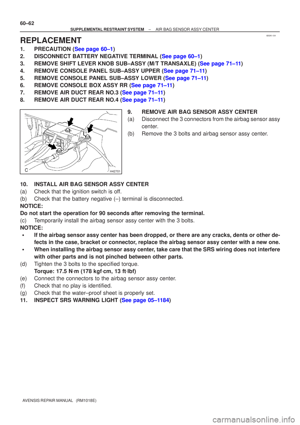
8.REMOVE AIR DUCT REAR NO.4 (See page 71±11) 9. REMOVE AIR BAG SENSOR ASSY CENTER
(a) Disconnect the 3 connectors from the airbag sensor assycenter.
(b) Remove the 3 bolts and airbag sensor assy center.
10. INSTALL AIR BAG SENSOR ASSY CENTER
(a) Check that the ignition switch is off.
(b) Check that the battery negative (±) terminal is disconnected.
NOTICE:
Do not start the operation for 90 seconds after removing the terminal.
(c) Temporarily install the airbag sensor assy center with the 3 bolts.
NOTICE:
�If the airbag sensor assy center has been dropped, or there are any crac\
ks, dents or other de-
fects in the case, bracket or connector, replace the airbag sensor assy center with a new one.
�When installing the airbag sensor assy center, take care that the SRS wiring does not interfere
with other parts and is not pinched between other parts.
(d) Tighten the 3 bolts to the specified torque. Torque: 17.5 N �m (178 kgf �cm, 13 ft �lbf)
(e) Connect the connectors to the airbag sensor assy center.
(f) Check that no play is identified.
(g) Check that the water±proof sheet is properly set.
11.INSPECT SRS WARNING LIGHT (See page 05±1184)
Page 1486 of 1690
600K6±01
H42699
60±64
±
SUPPLEMENTAL RESTRAINT SYSTEM AIR BAG SENSOR FRONT LH
AVENSIS REPAIR MANUAL (RM1018E)
REPLACEMENT
HINT:
Replacement procedure of the RH side is the same as that for with LH side.
1.PRECAUTION (See page 60±1)
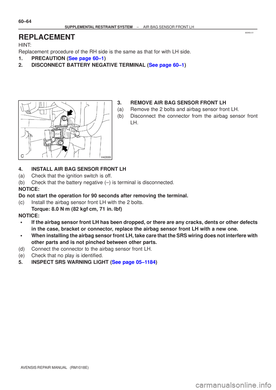
2.DISCONNECT BATTERY NEGATIVE TERMINAL (See page 60±1) 3. REMOVE AIR BAG SENSOR FRONT LH
(a) Remove the 2 bolts and airbag sensor front LH.
(b) Disconnect the connector from the airbag sensor frontLH.
4. INSTALL AIR BAG SENSOR FRONT LH
(a) Check that the ignition switch is off.
(b) Check that the battery negative (±) is terminal is disconnected.
NOTICE:
Do not start the operation for 90 seconds after removing the terminal.
(c) Install the airbag sensor front LH with the 2 bolts. Torque: 8.0 N �m (82 kgf �cm, 71 in. �lbf)
NOTICE:
�If the airbag sensor front LH has been dropped, or there are any cracks,\
dents or other defects
in the case, bracket or connector, replace the airbag sensor front LH with a new one.
�When installing the airbag sensor front LH, take care that the SRS wiring does not interfere\
with
other parts and is not pinched between other parts.
(d) Connect the connector to the airbag sensor front LH.
(e) Check that no play is identified.
5.INSPECT SRS WARNING LIGHT (See page 05±1184)