Page 851 of 1767
ZD30DDTi ENGINE MODELS
YEL066D
HEADLAMP Ð Daytime Light System Ð
Wiring Diagram Ð DTRL Ð (Cont'd)
EL-35
Page 852 of 1767
ZD30DDTi ENGINE MODELS
YEL067D
HEADLAMP Ð Daytime Light System Ð
Wiring Diagram Ð DTRL Ð (Cont'd)
EL-36
Page 853 of 1767
Description
IThe vertical direction of the headlamp projection can be adjusted from inside the vehicle to prevent the
headlamp beam axis from facing upward due to a change in the number of occupants and load conditions
in the vehicle.
IA little Electronic Control Unit (ECU) is incorporated in each actuator (one for each headlamp), which
compares a signal voltage (V
signal), coming from the headlamp aiming switch, with battery voltage (12V).
The signal voltage varies with the position of the switch.
Related to the difference in voltage the actuator rod will move more or less and adjust the headlamp beam
angle accordingly.
EEL018
HEADLAMP Ð Headlamp Aiming Control Ð
EL-37
Page 854 of 1767
Replacing Headlamp Aiming Actuator
Headlamp aiming actuator can not be disassembled.
To remove aiming actuator, turn it 90É to the center of the vehicle
(left and right symmetrical) and pull outward.
EEL017
EEL019
HEADLAMP Ð Headlamp Aiming Control Ð
Description (Cont'd)
EL-38
Page 855 of 1767
Wiring Diagram Ð H/AIM Ð
YEL068D
HEADLAMP Ð Headlamp Aiming Control Ð
EL-39
Page 856 of 1767
LHD MODELS
YEL069D
HEADLAMP Ð Headlamp Aiming Control Ð
Wiring Diagram Ð H/AIM Ð (Cont'd)
EL-40
Page 857 of 1767
RHD MODELS
YEL070D
HEADLAMP Ð Headlamp Aiming Control Ð
Wiring Diagram Ð H/AIM Ð (Cont'd)
EL-41
Page 858 of 1767

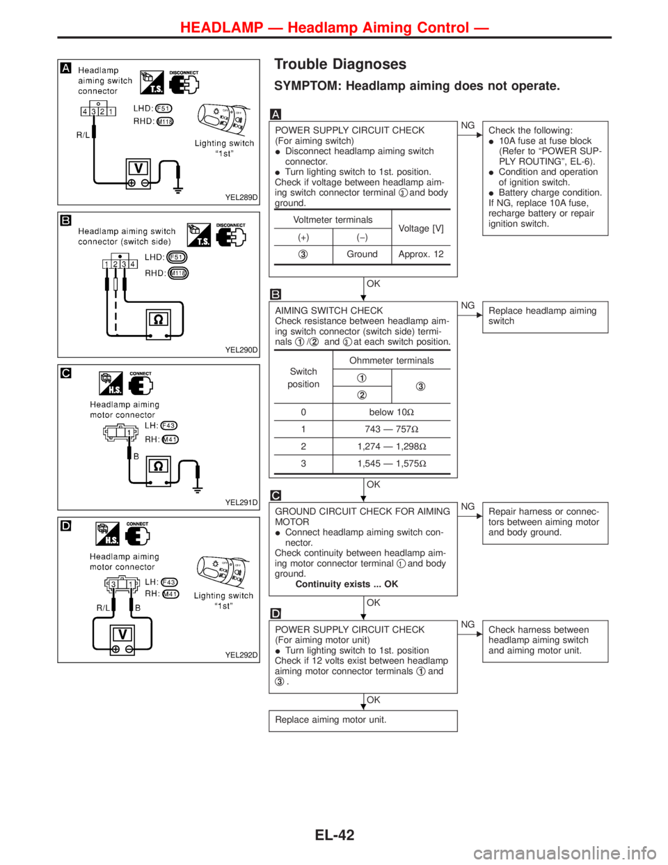
Trouble Diagnoses
SYMPTOM: Headlamp aiming does not operate.
POWER SUPPLY CIRCUIT CHECK
(For aiming switch)
IDisconnect headlamp aiming switch
connector.
ITurn lighting switch to 1st. position.
Check if voltage between headlamp aim-
ing switch connector terminalq
3and body
ground.
OK
ENG
Check the following:
I10A fuse at fuse block
(Refer to ªPOWER SUP-
PLY ROUTINGº, EL-6).
ICondition and operation
of ignition switch.
IBattery charge condition.
If NG, replace 10A fuse,
recharge battery or repair
ignition switch.
AIMING SWITCH CHECK
Check resistance between headlamp aim-
ing switch connector (switch side) termi-
nalsq
1/q2andq3at each switch position.
OK
ENG
Replace headlamp aiming
switch
GROUND CIRCUIT CHECK FOR AIMING
MOTOR
IConnect headlamp aiming switch con-
nector.
Check continuity between headlamp aim-
ing motor connector terminalq
1and body
ground.
Continuity exists ... OK
OK
ENG
Repair harness or connec-
tors between aiming motor
and body ground.
POWER SUPPLY CIRCUIT CHECK
(For aiming motor unit)
ITurn lighting switch to 1st. position
Check if 12 volts exist between headlamp
aiming motor connector terminalsq
1and
q3.
OK
ENG
Check harness between
headlamp aiming switch
and aiming motor unit.
Replace aiming motor unit.
Voltmeter terminals
Voltage [V]
(+) (þ)
q
3Ground Approx. 12
Switch
positionOhmmeter terminals
q1q3q2
0 below 10W
1 743 Ð 757W
2 1,274 Ð 1,298W
3 1,545 Ð 1,575W
YEL289D
YEL290D
YEL291D
YEL292D
H
H
H
H
HEADLAMP Ð Headlamp Aiming Control Ð
EL-42