2002 NISSAN TERRANO reset
[x] Cancel search: resetPage 893 of 1767

Check items Display Remarks
I) Fuel warning lamp test
SEL443X
Fuel warning lamp is on and odo trip meter segment ªFUELº
flashes.
Failure Chart for ªError 1º and ªError Eº
Bit Detectable items Description of the failureDisplayed figure on the
bit
Failure No failure
0Speedometer input
signalNo input signal
When no signal is detected for 30 minutes continuously with
the ignition ON, it should be judged as signal failure.
(If input signal is detected later, then the judgement will be
canceled immediately.)1
0
Abnormal input signal
When any signal of frequency which would not exist in normal
conditions is detected, it should be judged as signal failure.2
1Tachometer input
signalNo input signal
When no signal is detected for 30 minutes continuously with
the ignition ON, it should be judged as signal failure.
(If input signal is detected later, then the judgement will be
canceled immediately.)1
0
Abnormal input signal
When any signal of frequency which would not exist in normal
conditions is detected, it should be judged as signal failure.2
2Fuel level input sig-
nalShort circuit
When short circuit of the signal line is detected for 5 seconds
or more, it should be judged as short-circuit failure.1
0
Open circuit
When open circuit of the signal line is detected for 5 seconds
or more, it should be judged as open-circuit failure.2
3Water temperature
input signalShort circuit
When short circuit of the signal line is detected for 5 seconds
or more, it should be judged as short-circuit failure.10
4Outside air tempera-
ture input signalShort circuit
When short circuit of the signal line is detected for 5 seconds
or more, it should be judged as short-circuit failure.1
0
Open circuit
When open circuit of the signal line is detected for 5 seconds
or more, it should be judged as open-circuit failure.2
5Reset buttons Short circuit for reset buttons
When the short circuit is continu-
ously detected for 5 minutes or
more, it should be judged as
short-circuit failure.Right side reset button has
failed.1
0 Left side reset button has
failed.2
Both reset buttons have
failed.3
6Ð Ð 00
7CPU EEPROM failure 1
0
CPU RAM failure 2
METER AND GAUGES
Combination Meter Self-Diagnosis (Cont'd)
EL-77
Page 927 of 1767
System Description
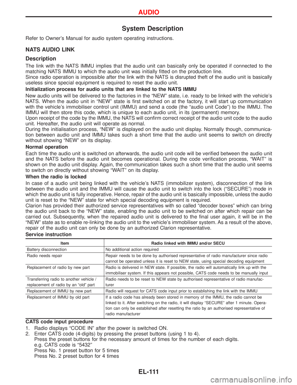
Refer to Owner's Manual for audio system operating instructions.
NATS AUDIO LINK
Description
The link with the NATS IMMU implies that the audio unit can basically only be operated if connected to the
matching NATS IMMU to which the audio unit was initially fitted on the production line.
Since radio operation is impossible after the link with the NATS is disrupted theft of the audio unit is basically
useless since special equipment is required to reset the audio unit.
Initialization process for audio units that are linked to the NATS IMMU
New audio units will be delivered to the factories in the ªNEWº state, i.e. ready to be linked with the vehicle's
NATS. When the audio unit in ªNEWº state is first switched on at the factory, it will start up communication
with the vehicle's immobiliser control unit (IMMU) and send a code (the ªaudio unit Codeº) to the IMMU. The
IMMU will then store this code, which is unique to each audio unit, in its (permanent) memory.
Upon receipt of the code by the IMMU, the NATS will confirm correct receipt of the audio unit code to the audio
unit. Hereafter, the audio unit will operate as normal.
During the initialisation process, ªNEWº is displayed on the audio unit display. Normally though, communica-
tion between audio unit and IMMU takes such a short time that the audio unit seems to switch on directly
without showing ªNEWº on its display.
Normal operation
Each time the audio unit is switched on afterwards, the audio unit code will be verified between the audio unit
and the NATS before the audio unit becomes operational. During the code verification process, ªWAITº is
shown on the audio unit display. Again, the communication takes such a short time that the audio unit seems
to switch on directly without showing ªWAITº on its display.
When the radio is locked
In case of a audio unit being linked with the vehicle's NATS (immobilizer system), disconnection of the link
between the audio unit and the IMMU will cause the audio unit to switch into the lock (ªSECUREº) mode in
which the audio unit is fully inoperative. Hence, repair of the audio unit is basically impossible, unless the audio
unit is reset to the ªNEWº state for which special decoding equipment is required.
Clarion has provided their authorized service representatives with so called ªdecoder boxesº which can bring
the audio unit back to the ªNEWº state, enabling the audio unit to be switched on after which repair can be
carried out. Subsequently, when the repaired audio unit is delivered to the final user again, it will be in the
ªNEWº state as to enable re-linking the audio unit to the vehicle's immobiliser system. As a result of the above,
repair of the audio unit can only be done by an authorized Clarion representative.
Service instruction
Item Radio linked with IMMU and/or SECU
Battery disconnection No additional action required
Radio needs repair Repair needs to be done by authorised representative of radio manufacturer since radio
cannot be operated unless it is reset to NEW state, using special decoding equipment
Replacement of radio by new part Radio is delivered in NEW state. If possible, the radio will automatically link up with the
immobiliser system. If this appears not possible, CATS code needs to be manually input
Transferring radio to another vehicle /
replacement of radio by an ªoldº partRadio needs to be reset to NEW state by authorised representative of radio manufac-
turer
Replacement of IMMU by new part Radio will request for CATS code input prior to establishing the link with the IMMU
Replacement of IMMU by old part If a radio code has already been stored in memory of the IMMU, the radio cannot be
linked to it. After switching on the radio, it will display ªSECUREº after 1 minute. Opera-
tion can only be established after resetting the ratio by an authorised representative of
radio manufacturer
CATS code input procedure
1. Radio displays ªCODE INº after the power is switched ON.
2. Enter CATS code (4-digits) by pressing the preset buttons (using 1 to 4).
Press the preset buttons for the necessary amount of times for the number of each digits.
e.g. CATS code is ª5432º
Press No. 1 preset button for 5 times
Press No. 2 preset button for 4 times
AUDIO
EL-111
Page 928 of 1767

Press No. 3 preset button for 3 times
Press No. 4 preset button for 2 times
3. Press the
button.
4. If the code is OK, the radio will power ON.
If the code is NG, the radio will be locked up as below. After the lock up, the radio will display ªCODE INº
again.
1st to 3rd attempt: The radio will be locked for 10 seconds after each attempt
4th to 20th attempt: The radio will be locked for 60 minutes after each attempt
Over 20th attempt: The radio will be locked completely
AUDIO
System Description (Cont'd)
EL-112
Page 940 of 1767
Trouble Diagnoses
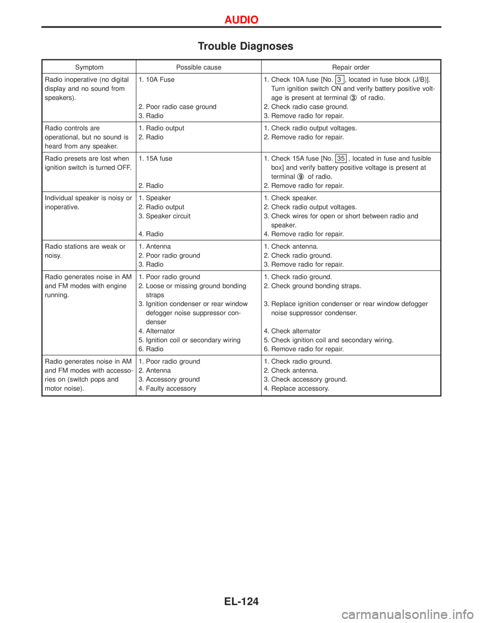
Symptom Possible cause Repair order
Radio inoperative (no digital
display and no sound from
speakers).1. 10A Fuse
2. Poor radio case ground
3. Radio1. Check 10A fuse [No.
3 , located in fuse block (J/B)].
Turn ignition switch ON and verify battery positive volt-
age is present at terminalq
3of radio.
2. Check radio case ground.
3. Remove radio for repair.
Radio controls are
operational, but no sound is
heard from any speaker.1. Radio output
2. Radio1. Check radio output voltages.
2. Remove radio for repair.
Radio presets are lost when
ignition switch is turned OFF.1. 15A fuse
2. Radio1. Check 15A fuse [No.
35 , located in fuse and fusible
box] and verify battery positive voltage is present at
terminalq
9of radio.
2. Remove radio for repair.
Individual speaker is noisy or
inoperative.1. Speaker
2. Radio output
3. Speaker circuit
4. Radio1. Check speaker.
2. Check radio output voltages.
3. Check wires for open or short between radio and
speaker.
4. Remove radio for repair.
Radio stations are weak or
noisy.1. Antenna
2. Poor radio ground
3. Radio1. Check antenna.
2. Check radio ground.
3. Remove radio for repair.
Radio generates noise in AM
and FM modes with engine
running.1. Poor radio ground
2. Loose or missing ground bonding
straps
3. Ignition condenser or rear window
defogger noise suppressor con-
denser
4. Alternator
5. Ignition coil or secondary wiring
6. Radio1. Check radio ground.
2. Check ground bonding straps.
3. Replace ignition condenser or rear window defogger
noise suppressor condenser.
4. Check alternator
5. Check ignition coil and secondary wiring.
6. Remove radio for repair.
Radio generates noise in AM
and FM modes with accesso-
ries on (switch pops and
motor noise).1. Poor radio ground
2. Antenna
3. Accessory ground
4. Faulty accessory1. Check radio ground.
2. Check antenna.
3. Check accessory ground.
4. Replace accessory.
AUDIO
EL-124
Page 941 of 1767
CD AUTOCHANGER
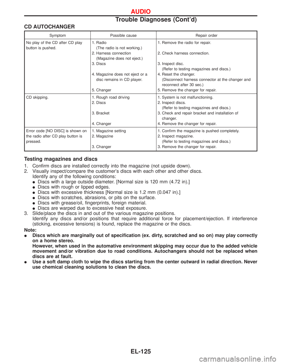
Symptom Possible cause Repair order
No play of the CD after CD play
button is pushed.1. Radio
(The radio is not working.)
2. Harness connection
(Magazine does not eject.)
3. Discs
4. Magazine does not eject or a
disc remains in CD player.
5. Changer1. Remove the radio for repair.
2. Check harness connection.
3. Inspect disc.
(Refer to testing magazines and discs.)
4. Reset the changer.
(Disconnect harness connector at the changer and
reconnect after 30 sec.)
5. Remove the changer for repair.
CD skipping. 1. Rough road driving
2. Discs
3. Bracket
4. Changer1. System is not malfunctioning.
2. Inspect discs.
(Refer to testing magazines and discs.)
3. Check and repair bracket and installation of
changer.
4. Remove the changer for repair.
Error code [NO DISC] is shown on
the radio after CD play button is
pressed.1. Magazine setting
2. Magazine
3. Changer1. Confirm the magazine is pushed completely.
2. Inspect magazine.
(Refer to testing magazines and discs.)
3. Remove the changer for repair.
Testing magazines and discs
1. Confirm discs are installed correctly into the magazine (not upside down).
2. Visually inspect/compare the customer's discs with each other and other discs.
Identify any of the following conditions:
IDiscs with a large outside diameter. [Normal size is 120 mm (4.72 in).]
IDiscs with rough or lipped edges.
IDiscs with excessive thickness [Normal size is 1.2 mm (0.047 in).]
IDiscs with scratches, abrasions, or pits on the surface.
IDiscs with grease/oil, fingerprints, foreign material.
IDiscs are warped due to excessive heat exposure.
3. Slide/place the discs in and out of the various magazine positions.
Identify any discs and/or positions that require additional force for placement/ejection. If interference
(sticking, excessive tensions) is found, replace the magazine or the discs.
Note:
IDiscs which are marginally out of specification (ex. dirty, scratched and so on) may play correctly
on a home stereo.
However, when used in the automative environment skipping may occur due to the added vehicle
movement and/or vibration due to road conditions. Autochangers should not be replaced when
discs are at fault.
IUse a soft damp cloth to wipe the discs starting from the center outward in radial direction. Never
use chemical cleaning solutions to clean the discs.
AUDIO
Trouble Diagnoses (Cont'd)
EL-125
Page 997 of 1767
FUNCTION
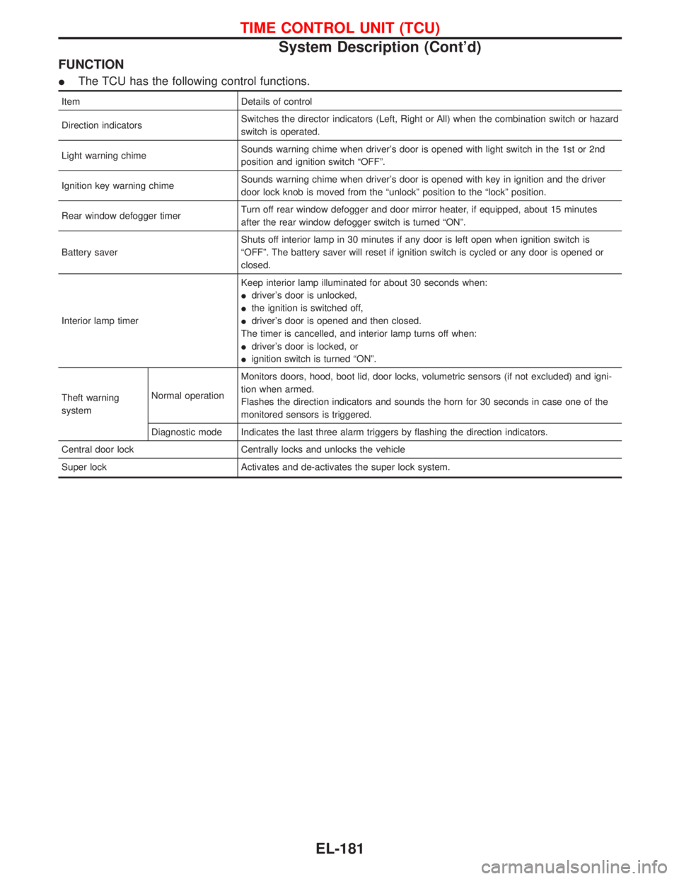
IThe TCU has the following control functions.
Item Details of control
Direction indicatorsSwitches the director indicators (Left, Right or All) when the combination switch or hazard
switch is operated.
Light warning chimeSounds warning chime when driver's door is opened with light switch in the 1st or 2nd
position and ignition switch ªOFFº.
Ignition key warning chimeSounds warning chime when driver's door is opened with key in ignition and the driver
door lock knob is moved from the ªunlockº position to the ªlockº position.
Rear window defogger timerTurn off rear window defogger and door mirror heater, if equipped, about 15 minutes
after the rear window defogger switch is turned ªONº.
Battery saverShuts off interior lamp in 30 minutes if any door is left open when ignition switch is
ªOFFº. The battery saver will reset if ignition switch is cycled or any door is opened or
closed.
Interior lamp timerKeep interior lamp illuminated for about 30 seconds when:
Idriver's door is unlocked,
Ithe ignition is switched off,
Idriver's door is opened and then closed.
The timer is cancelled, and interior lamp turns off when:
Idriver's door is locked, or
Iignition switch is turned ªONº.
Theft warning
systemNormal operationMonitors doors, hood, boot lid, door locks, volumetric sensors (if not excluded) and igni-
tion when armed.
Flashes the direction indicators and sounds the horn for 30 seconds in case one of the
monitored sensors is triggered.
Diagnostic mode Indicates the last three alarm triggers by flashing the direction indicators.
Central door lock Centrally locks and unlocks the vehicle
Super lock Activates and de-activates the super lock system.
TIME CONTROL UNIT (TCU)
System Description (Cont'd)
EL-181
Page 1647 of 1767
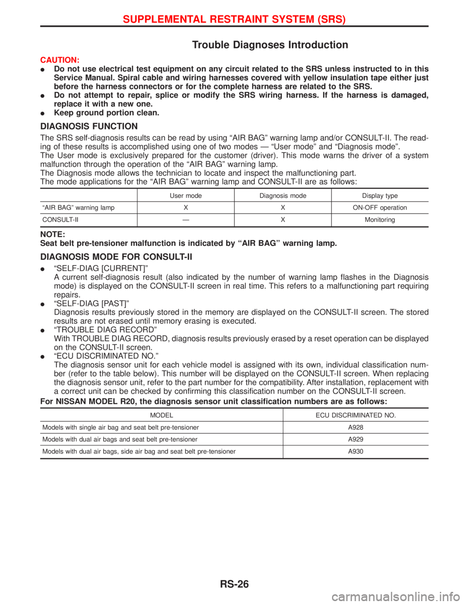
Trouble Diagnoses Introduction
CAUTION:
IDo not use electrical test equipment on any circuit related to the SRS unless instructed to in this
Service Manual. Spiral cable and wiring harnesses covered with yellow insulation tape either just
before the harness connectors or for the complete harness are related to the SRS.
IDo not attempt to repair, splice or modify the SRS wiring harness. If the harness is damaged,
replace it with a new one.
IKeep ground portion clean.
DIAGNOSIS FUNCTION
The SRS self-diagnosis results can be read by using ªAIR BAGº warning lamp and/or CONSULT-II. The read-
ing of these results is accomplished using one of two modes Ð ªUser modeº and ªDiagnosis modeº.
The User mode is exclusively prepared for the customer (driver). This mode warns the driver of a system
malfunction through the operation of the ªAIR BAGº warning lamp.
The Diagnosis mode allows the technician to locate and inspect the malfunctioning part.
The mode applications for the ªAIR BAGº warning lamp and CONSULT-II are as follows:
User mode Diagnosis mode Display type
ªAIR BAGº warning lamp X X ON-OFF operation
CONSULT-II Ð X Monitoring
NOTE:
Seat belt pre-tensioner malfunction is indicated by ªAIR BAGº warning lamp.
DIAGNOSIS MODE FOR CONSULT-II
IªSELF-DIAG [CURRENT]º
A current self-diagnosis result (also indicated by the number of warning lamp flashes in the Diagnosis
mode) is displayed on the CONSULT-II screen in real time. This refers to a malfunctioning part requiring
repairs.
IªSELF-DIAG [PAST]º
Diagnosis results previously stored in the memory are displayed on the CONSULT-II screen. The stored
results are not erased until memory erasing is executed.
IªTROUBLE DIAG RECORDº
With TROUBLE DIAG RECORD, diagnosis results previously erased by a reset operation can be displayed
on the CONSULT-II screen.
IªECU DISCRIMINATED NO.º
The diagnosis sensor unit for each vehicle model is assigned with its own, individual classification num-
ber (refer to the table below). This number will be displayed on the CONSULT-II screen. When replacing
the diagnosis sensor unit, refer to the part number for the compatibility. After installation, replacement with
a correct unit can be checked by confirming this classification number on the CONSULT-II screen.
For NISSAN MODEL R20, the diagnosis sensor unit classification numbers are as follows:
MODEL ECU DISCRIMINATED NO.
Models with single air bag and seat belt pre-tensioner A928
Models with dual air bags and seat belt pre-tensioner A929
Models with dual air bags, side air bag and seat belt pre-tensioner A930
SUPPLEMENTAL RESTRAINT SYSTEM (SRS)
RS-26
Page 1665 of 1767
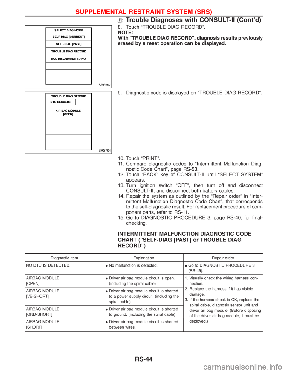
8. Touch ªTROUBLE DIAG RECORDº.
NOTE:
With ªTROUBLE DIAG RECORDº, diagnosis results previously
erased by a reset operation can be displayed.
9. Diagnostic code is displayed on ªTROUBLE DIAG RECORDº.
10. Touch ªPRINTº.
11. Compare diagnostic codes to ªIntermittent Malfunction Diag-
nostic Code Chartº, page RS-53.
12. Touch ªBACKº key of CONSULT-II until ªSELECT SYSTEMº
appears.
13. Turn ignition switch ªOFFº, then turn off and disconnect
CONSULT-II, and disconnect both battery cables.
14. Repair the system as outlined by the ªRepair orderº in ªInter-
mittent Malfunction Diagnostic Code Chartº, that corresponds
to the self-diagnostic result. For replacement procedure of com-
ponent parts, refer to RS-11.
15. Go to DIAGNOSTIC PROCEDURE 3, page RS-40, for final-
checking.
INTERMITTENT MALFUNCTION DIAGNOSTIC CODE
CHART (ªSELF-DIAG [PAST] or TROUBLE DIAG
RECORDº)
Diagnostic item Explanation Repair order
NO DTC IS DETECTED.INo malfunction is detected.IGo to DIAGNOSTIC PROCEDURE 3
(RS-49).
AIRBAG MODULE
[OPEN]IDriver air bag module circuit is open.
(including the spiral cable)1. Visually check the wiring harness con-
nection.
2. Replace the harness if it has visible
damage.
3. If the harness check is OK, replace the
spiral cable, diagnosis sensor unit and
driver air bag module. (Before disposing
of the driver air bag module, it must be
deployed.) AIRBAG MODULE
[VB-SHORT]IDriver air bag module circuit is shorted
to a power supply circuit. (including the
spiral cable)
AIRBAG MODULE
[GND-SHORT]IDriver air bag module circuit is shorted
to ground. (including the spiral cable)
AIRBAG MODULE
[SHORT]IDriver air bag module circuit is shorted
between wires.
SRS697
SRS704
SUPPLEMENTAL RESTRAINT SYSTEM (SRS)
Trouble Diagnoses with CONSULT-II (Cont'd)
RS-44