2002 NISSAN TERRANO checking oil
[x] Cancel search: checking oilPage 1320 of 1767
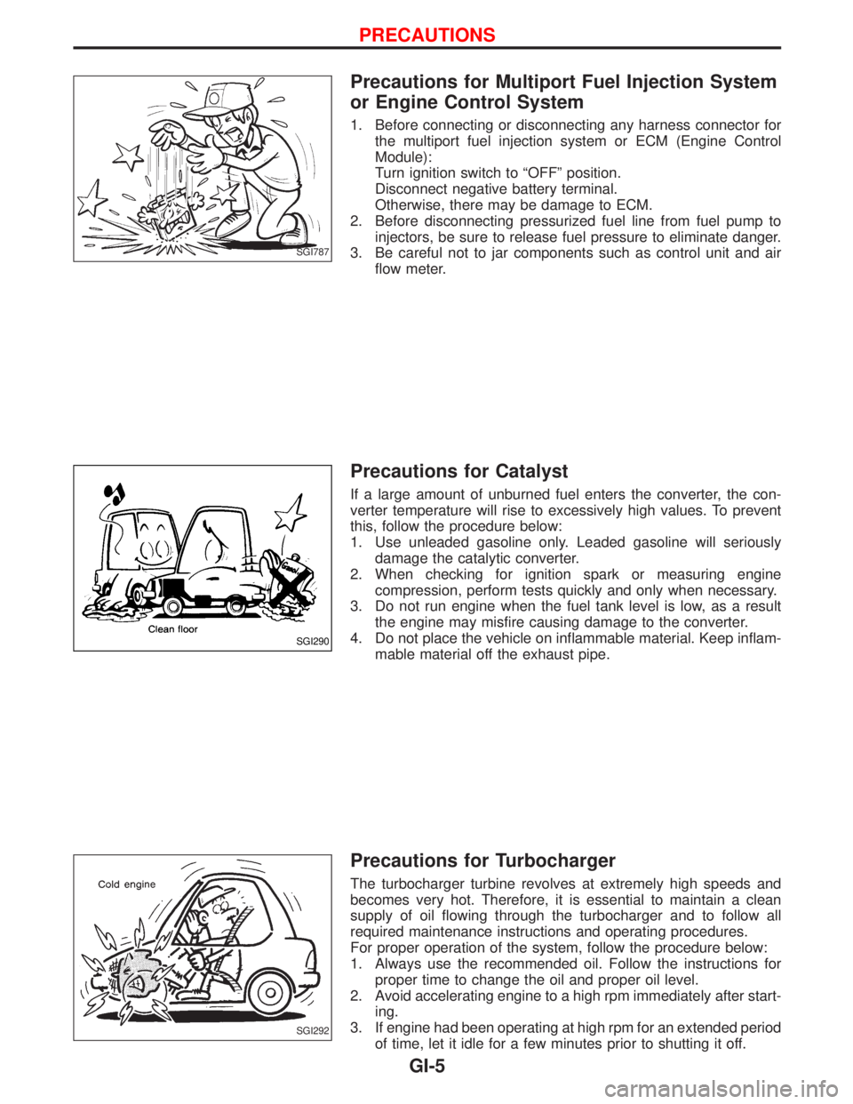
Precautions for Multiport Fuel Injection System
or Engine Control System
1. Before connecting or disconnecting any harness connector for
the multiport fuel injection system or ECM (Engine Control
Module):
Turn ignition switch to ªOFFº position.
Disconnect negative battery terminal.
Otherwise, there may be damage to ECM.
2. Before disconnecting pressurized fuel line from fuel pump to
injectors, be sure to release fuel pressure to eliminate danger.
3. Be careful not to jar components such as control unit and air
flow meter.
Precautions for Catalyst
If a large amount of unburned fuel enters the converter, the con-
verter temperature will rise to excessively high values. To prevent
this, follow the procedure below:
1. Use unleaded gasoline only. Leaded gasoline will seriously
damage the catalytic converter.
2. When checking for ignition spark or measuring engine
compression, perform tests quickly and only when necessary.
3. Do not run engine when the fuel tank level is low, as a result
the engine may misfire causing damage to the converter.
4. Do not place the vehicle on inflammable material. Keep inflam-
mable material off the exhaust pipe.
Precautions for Turbocharger
The turbocharger turbine revolves at extremely high speeds and
becomes very hot. Therefore, it is essential to maintain a clean
supply of oil flowing through the turbocharger and to follow all
required maintenance instructions and operating procedures.
For proper operation of the system, follow the procedure below:
1. Always use the recommended oil. Follow the instructions for
proper time to change the oil and proper oil level.
2. Avoid accelerating engine to a high rpm immediately after start-
ing.
3. If engine had been operating at high rpm for an extended period
of time, let it idle for a few minutes prior to shutting it off.
SGI787
SGI290
SGI292
PRECAUTIONS
GI-5
Page 1324 of 1767
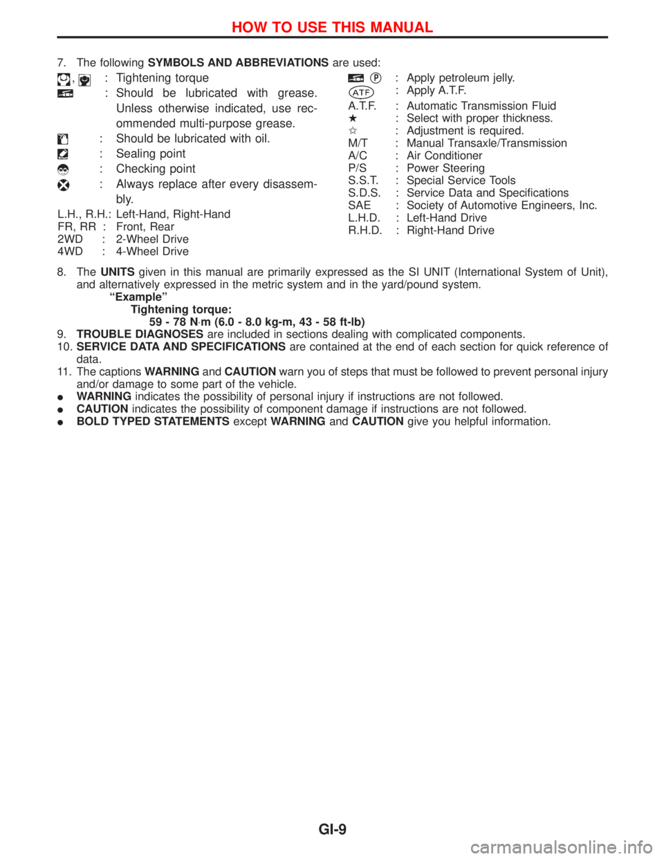
7. The followingSYMBOLS AND ABBREVIATIONSare used:
,: Tightening torque
: Should be lubricated with grease.
Unless otherwise indicated, use rec-
ommended multi-purpose grease.
: Should be lubricated with oil.
: Sealing point
: Checking point
: Always replace after every disassem-
bly.
L.H., R.H.: Left-Hand, Right-Hand
FR, RR : Front, Rear
2WD : 2-Wheel Drive
4WD : 4-Wheel Drive
qP: Apply petroleum jelly.
: Apply A.T.F.
A.T.F. : Automatic Transmission Fluid
H: Select with proper thickness.
I: Adjustment is required.
M/T : Manual Transaxle/Transmission
A/C : Air Conditioner
P/S : Power Steering
S.S.T. : Special Service Tools
S.D.S. : Service Data and Specifications
SAE : Society of Automotive Engineers, Inc.
L.H.D. : Left-Hand Drive
R.H.D. : Right-Hand Drive
8. TheUNITSgiven in this manual are primarily expressed as the SI UNIT (International System of Unit),
and alternatively expressed in the metric system and in the yard/pound system.
ªExampleº
Tightening torque:
59-78N×m (6.0 - 8.0 kg-m, 43 - 58 ft-lb)
9.TROUBLE DIAGNOSESare included in sections dealing with complicated components.
10.SERVICE DATA AND SPECIFICATIONSare contained at the end of each section for quick reference of
data.
11. The captionsWARNINGandCAUTIONwarn you of steps that must be followed to prevent personal injury
and/or damage to some part of the vehicle.
IWARNINGindicates the possibility of personal injury if instructions are not followed.
ICAUTIONindicates the possibility of component damage if instructions are not followed.
IBOLD TYPED STATEMENTSexceptWARNINGandCAUTIONgive you helpful information.
HOW TO USE THIS MANUAL
GI-9
Page 1354 of 1767
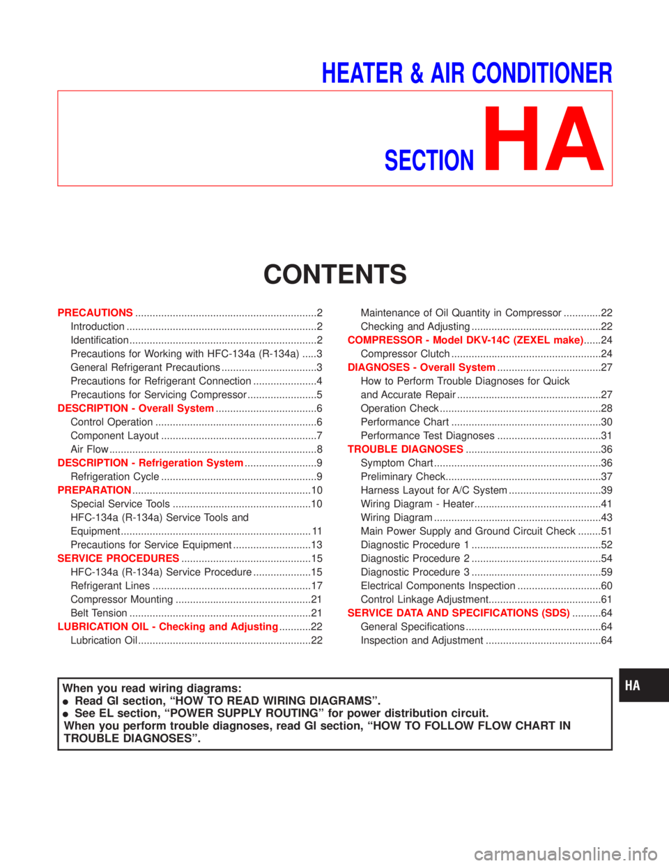
HEATER & AIR CONDITIONER
SECTION
HA
CONTENTS
PRECAUTIONS...............................................................2
Introduction ..................................................................2
Identification .................................................................2
Precautions for Working with HFC-134a (R-134a) .....3
General Refrigerant Precautions .................................3
Precautions for Refrigerant Connection ......................4
Precautions for Servicing Compressor ........................5
DESCRIPTION - Overall System...................................6
Control Operation ........................................................6
Component Layout ......................................................7
Air Flow ........................................................................8
DESCRIPTION - Refrigeration System.........................9
Refrigeration Cycle ......................................................9
PREPARATION..............................................................10
Special Service Tools ................................................10
HFC-134a (R-134a) Service Tools and
Equipment .................................................................. 11
Precautions for Service Equipment ...........................13
SERVICE PROCEDURES.............................................15
HFC-134a (R-134a) Service Procedure ....................15
Refrigerant Lines .......................................................17
Compressor Mounting ...............................................21
Belt Tension ...............................................................21
LUBRICATION OIL - Checking and Adjusting...........22
Lubrication Oil ............................................................22Maintenance of Oil Quantity in Compressor .............22
Checking and Adjusting .............................................22
COMPRESSOR - Model DKV-14C (ZEXEL make)......24
Compressor Clutch ....................................................24
DIAGNOSES - Overall System....................................27
How to Perform Trouble Diagnoses for Quick
and Accurate Repair ..................................................27
Operation Check ........................................................28
Performance Chart ....................................................30
Performance Test Diagnoses ....................................31
TROUBLE DIAGNOSES...............................................36
Symptom Chart ..........................................................36
Preliminary Check......................................................37
Harness Layout for A/C System ................................39
Wiring Diagram - Heater............................................41
Wiring Diagram ..........................................................43
Main Power Supply and Ground Circuit Check ........51
Diagnostic Procedure 1 .............................................52
Diagnostic Procedure 2 .............................................54
Diagnostic Procedure 3 .............................................59
Electrical Components Inspection .............................60
Control Linkage Adjustment.......................................61
SERVICE DATA AND SPECIFICATIONS (SDS)..........64
General Specifications ...............................................64
Inspection and Adjustment ........................................64
When you read wiring diagrams:
IRead GI section, ªHOW TO READ WIRING DIAGRAMSº.
ISee EL section, ªPOWER SUPPLY ROUTINGº for power distribution circuit.
When you perform trouble diagnoses, read GI section, ªHOW TO FOLLOW FLOW CHART IN
TROUBLE DIAGNOSESº.
Page 1369 of 1767
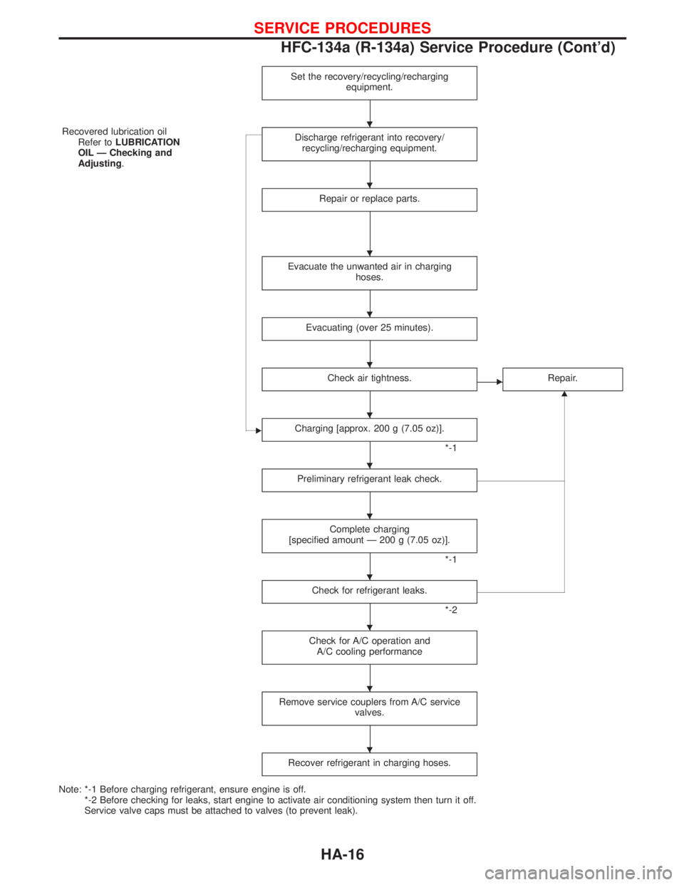
Set the recovery/recycling/recharging
equipment.
Recovered lubrication oil
Refer toLUBRICATION
OIL Ð Checking and
Adjusting.Discharge refrigerant into recovery/
recycling/recharging equipment.
Repair or replace parts.
Evacuate the unwanted air in charging
hoses.
Evacuating (over 25 minutes).
Check air tightness.ERepair.
G
ECharging [approx. 200 g (7.05 oz)].
*-1
Preliminary refrigerant leak check.
Complete charging
[specified amount Ð 200 g (7.05 oz)].
*-1
Check for refrigerant leaks.
*-2
Check for A/C operation and
A/C cooling performance
Remove service couplers from A/C service
valves.
Recover refrigerant in charging hoses.
Note: *-1 Before charging refrigerant, ensure engine is off.
*-2 Before checking for leaks, start engine to activate air conditioning system then turn it off.
Service valve caps must be attached to valves (to prevent leak).
H
H
H
H
H
H
H
H
H
H
H
H
SERVICE PROCEDURES
HFC-134a (R-134a) Service Procedure (Cont'd)
HA-16
Page 1375 of 1767
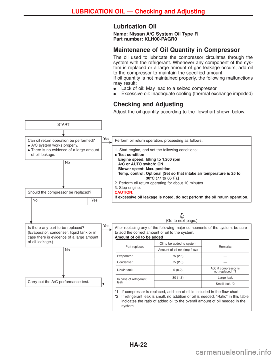
Lubrication Oil
Name: Nissan A/C System Oil Type R
Part number: KLH00-PAGR0
Maintenance of Oil Quantity in Compressor
The oil used to lubricate the compressor circulates through the
system with the refrigerant. Whenever any component of the sys-
tem is replaced or a large amount of gas leakage occurs, add oil
to the compressor to maintain the specified amount.
If oil quantity is not maintained properly, the following malfunctions
may result:
ILack of oil: May lead to a seized compressor
IExcessive oil: Inadequate cooling (thermal exchange impeded)
Checking and Adjusting
Adjust the oil quantity according to the flowchart shown below.
START
Can oil return operation be performed?
IA/C system works properly.
IThere is no evidence of a large amount
of oil leakage.
No
EYe s
Perform oil return operation, proceeding as follows:
-------------------------------------------------------------------------------------------------------------------------------------------------------------------------------------------------------------------------------------------------------------------------------------------------------------------------------------------------------------------------------------------------------------------------------------------------------------------------------------------------------------------------------------------------------------
1. Start engine, and set the following conditions:
ITest condition
Engine speed: Idling to 1,200 rpm
A/C or AUTO switch: ON
Blower speed: Max. position
Temp. control: Optional [Set so that intake air temperature is 25 to
30ÉC (77 to 86ÉF).]
2. Perform oil return operating for about 10 minutes.
3. Stop engine.
CAUTION:
If excessive oil leakage is noted, do not perform the oil return operation.
Should the compressor be replaced?
No Yes
qA(Go to next page.)
Is there any part to be replaced?
(Evaporator, condenser, liquid tank or in
case there is evidence of a large amount
of oil leakage.)
No
EYe s
After replacing any of the following major components of the system, be sure
to add the correct amount of oil to the system.
Amount of oil to be added
*1: If compressor is replaced, addition of oil is included in the flow chart.
*2: If refrigerant leak is small, no addition of oil is needed. ªRatioº in this table
indicates the ratio of added oil to the overall amount of oil needed in the
system.
Carry out the A/C performance test.F
Part replacedOil to be added to system
Remarks
Amount of oil m(Imp fl oz)
Evaporator 75 (2.6) Ð
Condenser 75 (2.6) Ð
Liquid tank 5 (0.2)Add if compressor is
not replaced. *1
In case of refrigerant
leak30 (1.1) Large leak
Ð Small leak *2
H
H
H
H
H
LUBRICATION OIL Ð Checking and Adjusting
HA-22
Page 1376 of 1767
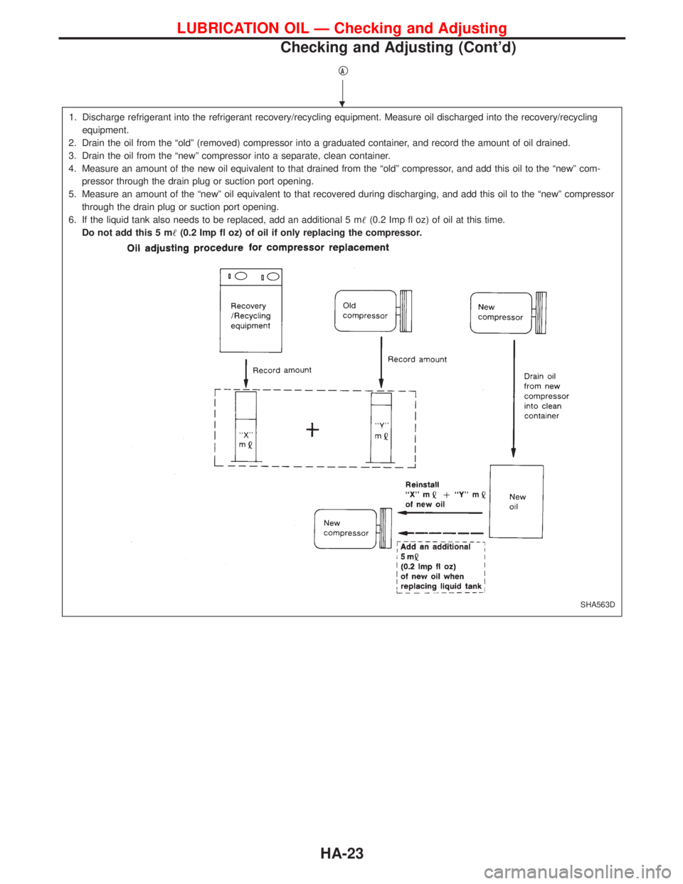
qA
1. Discharge refrigerant into the refrigerant recovery/recycling equipment. Measure oil discharged into the recovery/recycling
equipment.
2. Drain the oil from the ªoldº (removed) compressor into a graduated container, and record the amount of oil drained.
3. Drain the oil from the ªnewº compressor into a separate, clean container.
4. Measure an amount of the new oil equivalent to that drained from the ªoldº compressor, and add this oil to the ªnewº com-
pressor through the drain plug or suction port opening.
5. Measure an amount of the ªnewº oil equivalent to that recovered during discharging, and add this oil to the ªnewº compressor
through the drain plug or suction port opening.
6. If the liquid tank also needs to be replaced, add an additional 5 m(0.2 Imp fl oz) of oil at this time.
Do not add this 5 m(0.2 Imp fl oz) of oil if only replacing the compressor.
SHA563D
H
LUBRICATION OIL Ð Checking and Adjusting
Checking and Adjusting (Cont'd)
HA-23
Page 1407 of 1767
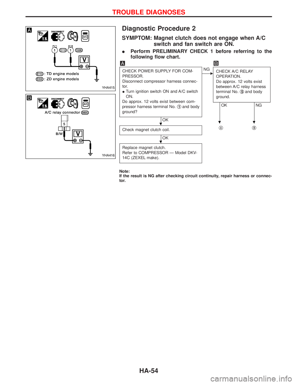
Diagnostic Procedure 2
SYMPTOM: Magnet clutch does not engage when A/C
switch and fan switch are ON.
IPerform PRELIMINARY CHECK 1 before referring to the
following flow chart.
CHECK POWER SUPPLY FOR COM-
PRESSOR.
Disconnect compressor harness connec-
tor.
ITurn ignition switch ON and A/C switch
ON.
Do approx. 12 volts exist between com-
pressor harness terminal No.q
1and body
ground?
OK
ENG
CHECK A/C RELAY
OPERATION.
Do approx. 12 volts exist
between A/C relay harness
terminal No.q
5and body
ground.
OK NG
Check magnet clutch coil.
OKq
AqB
Replace magnet clutch.
Refer to COMPRESSOR Ð Model DKV-
14C (ZEXEL make).
Note:
If the result is NG after checking circuit continuity, repair harness or connec-
tor.
YHA415
YHA416
HHH
H
TROUBLE DIAGNOSES
HA-54
Page 1408 of 1767
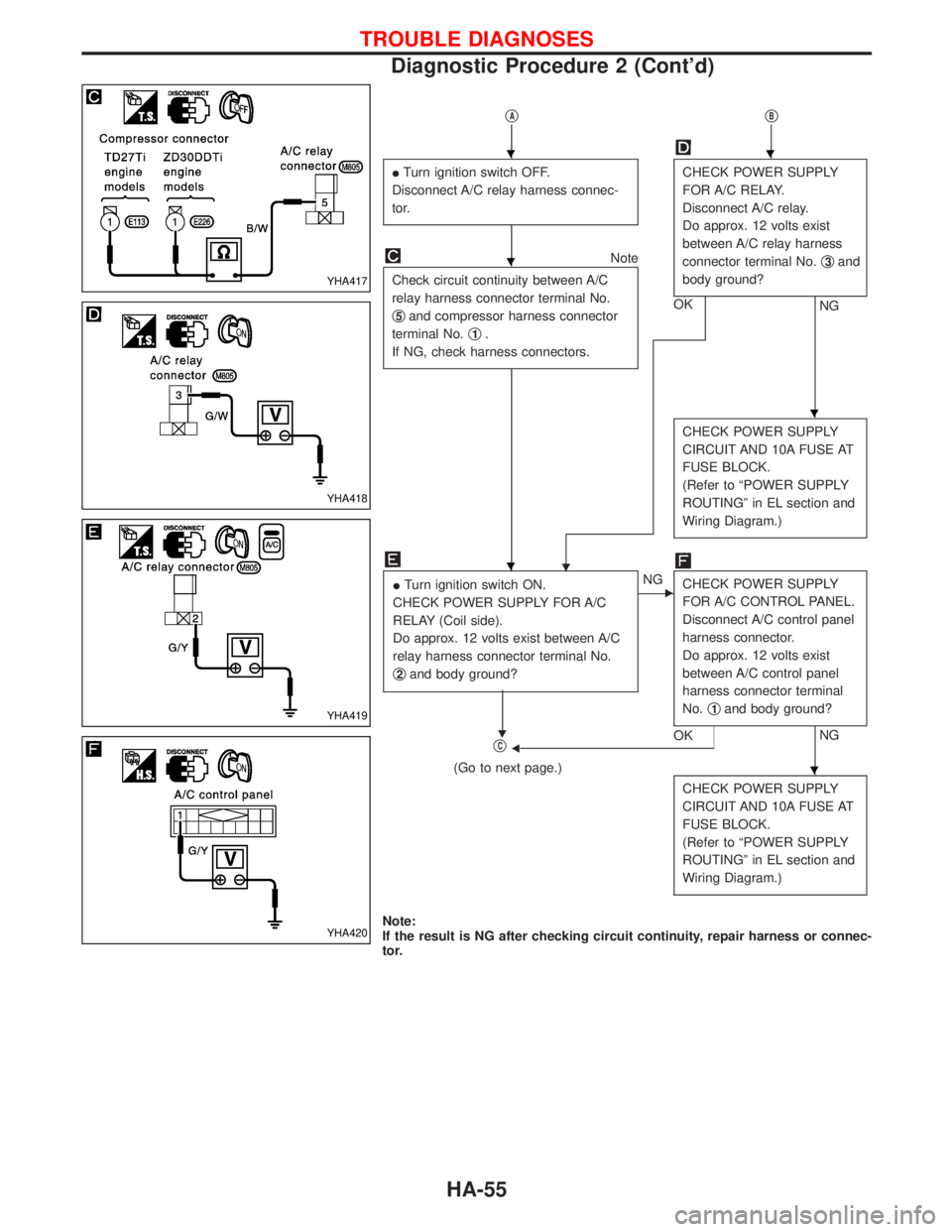
qAqB
ITurn ignition switch OFF.
Disconnect A/C relay harness connec-
tor.CHECK POWER SUPPLY
FOR A/C RELAY.
Disconnect A/C relay.
Do approx. 12 volts exist
between A/C relay harness
connector terminal No.q
3and
body ground?
NG OK
Note
Check circuit continuity between A/C
relay harness connector terminal No.
q
5and compressor harness connector
terminal No.q
1.
If NG, check harness connectors.
H
CHECK POWER SUPPLY
CIRCUIT AND 10A FUSE AT
FUSE BLOCK.
(Refer to ªPOWER SUPPLY
ROUTINGº in EL section and
Wiring Diagram.)
ITurn ignition switch ON.
CHECK POWER SUPPLY FOR A/C
RELAY (Coil side).
Do approx. 12 volts exist between A/C
relay harness connector terminal No.
q
2and body ground?
H
ENG
CHECK POWER SUPPLY
FOR A/C CONTROL PANEL.
Disconnect A/C control panel
harness connector.
Do approx. 12 volts exist
between A/C control panel
harness connector terminal
No.q
1and body ground?
NG
OKFqC
(Go to next page.)
CHECK POWER SUPPLY
CIRCUIT AND 10A FUSE AT
FUSE BLOCK.
(Refer to ªPOWER SUPPLY
ROUTINGº in EL section and
Wiring Diagram.)
Note:
If the result is NG after checking circuit continuity, repair harness or connec-
tor.
YHA417
YHA418
YHA419
YHA420
HH
H
H
H
H
TROUBLE DIAGNOSES
Diagnostic Procedure 2 (Cont'd)
HA-55