Page 55 of 235

functioning properly. Have the system
checked by your authorized NISSAN
dealer.
High beam indicator light
(Blue)
This blue light comes on when the headlight
high beam is on and goes out when the low
beam is selected.
The high beam indicator light also comes on
when the passing signal is activated.
Malfunction indicator lamp
(MIL)
If this indicator lamp comes on steady or
blinks while the engine is running, it may
indicate a potential emission control mal-
function.
The malfunction indicator lamp may also
come on steady if the fuel filler cap is loose
or missing, or if the vehicle runs out of fuel.
Check to make sure the fuel filler cap is
installed and closed tightly, and that the
vehicle has at least three gallons of fuel in
the fuel tank.
After a few driving trips, the
lamp
should turn off if no other potential emission
control system malfunction exists.
Operation
The malfunction indicator lamp will come on
in one of two ways:
cMalfunction indicator lamp on steady - An
emission control system malfunction has
been detected. Check the fuel filler cap. If
the fuel filler cap is loose or missing,
tighten or install the cap and continue to
drive the vehicle. The
lamp should
turn off after a few driving trips. If the
lamp does not turn off after a few
driving trips, have the vehicle inspected
by an authorized NISSAN dealer. You do
not need to have your vehicle towed to
the dealer.
cMalfunction indicator lamp blinking - An
engine misfire has been detected which
may damage the emission control sys-
tem. To reduce or avoid emission control
system damage:
a) do not drive at speeds above 45 MPH
(72 km/h).
b)
avoid hard acceleration or deceleration.
c) avoid steep uphill grades.
d) if possible, reduce the amount of cargo
being hauled or towed.
The malfunction indicator lamp may stop
blinking and come on steady. Have thevehicle inspected by an authorized NISSAN
dealer. You do not need to have your vehicle
towed to the dealer.
CAUTION
Continued vehicle operation without
having the emission control system
checked and repaired as necessary
could lead to poor driveability, reduced
fuel economy, and possible damage to
the emission control system.
Overdrive off indicator light
(automatic transmission only)
This light comes on when the overdrive
switch is in the OFF position.
Turn signal/hazard indicator
lights
The appropriate light flashes when the turn
signal lever switch is activated.
Both lights flash when the hazard switch is
turned on.
2-10Instruments and controls
ZX
Page 56 of 235

AUDIBLE REMINDERS
Key reminder chime
A chime sounds if the driver's side door is
opened while the key is left in the ignition
switch. Remove the key and take it with you
when leaving the vehicle.
Light reminder chime
With the ignition switch in the OFF position,
a chime sounds when the driver's side door
is opened if the headlights or parking lights
are on.
Turn the headlight control switch off before
leaving the vehicle.
Brake pad wear warning
The disc brake pads have an audible wear
warning. When a brake pad requires re-
placement, it makes a high pitched scraping
sound when the vehicle is in motion,
whether or not the brake pedal is de-
pressed. Have the brakes checked as soon
as possible if the warning sound is heard.Your vehicle has two types of security sys-
tems:
cNissan Vehicle Immobilizer System±
NVIS (if so equipped)
cVehicle security system (if so equipped)
NISSAN VEHICLE IMMOBILIZER
SYSTEM (NVIS) (if so equipped)
The Nissan Vehicle Immobilizer System
(NVIS) will not allow the engine to start
without the use of a registered NVIS key.
If the engine fails to start using a registered
NVIS key (for example, when interference iscaused by another NVIS key, an automated
toll road device or automated payment de-
vice on the key ring), restart the engine
using the following procedures:
1. Leave the ignition switch in the ON posi-
tion for approximately 5 seconds.
2. Turn the ignition switch to the OFF or
LOCK position, and wait approximately 5
seconds.
3. Repeat step 1 and 2.
4. Restart the engine while holding the de-
vice (which may have caused the inter-
ference) separate from the registered
NVIS key.
If the no start condition re-occurs, Nissan
recommends placing the registered NVIS
key on a separate key ring to avoid interfer-
ence from other devices.
Statement related to section 15 of FCC
rules for Nissan Vehicle Immobilizer
System (CONT ASSY - IMMOBILIZER,
ANT ASSY - IMMOBILIZER)
This device complies with part 15 of the
FCC Rules and RSS-210 of Industry
Canada. Operation is subject to the fol-
lowing two conditions;
IC0005
SECURITY SYSTEMS
Instruments and controls2-11
ZX
Page 57 of 235

(1) This device may not cause harmful
interference, and (2) this device must
accept any interference received, includ-
ing interference that may cause undes-
ired operation of the device.
CHANGES OR MODIFICATIONS NOT EX-
PRESSLY APPROVED BY THE MANU-
FACTURER FOR COMPLIANCE COULD
VOID THE USER'S AUTHORITY TO OP-
ERATE THE EQUIPMENT.
Security indicator light (Nissan Ve-
hicle Immobilizer System)
The security indicator light is located on the
instrument panel near the windshield.
The security indicator light blinks every 3
seconds whenever the ignition switch is in
the LOCK, OFF or ACC position. This func-
tion indicates the Nissan Vehicle Immobi-
lizer System (NVIS) is operational.
If the NVIS is malfunctioning, the light will
remain on while the ignition key is in the ON
position.If the light still remains on and/or the
engine will not start, see your Nissan
dealer for NVIS service as soon as pos-
sible. Please bring all NVIS keys that you
have when visiting your authorized NIS-
SAN dealer for service.
VEHICLE SECURITY SYSTEM (if
so equipped)
The vehicle security system provides visual
and audio alarm signals if parts of the
vehicle are disturbed.
LIC0047
2-12Instruments and controls
ZX
Page 61 of 235
To defog the rear window glass, start the
engine and push the rear window defogger
switch on. (The indicator light on the switch
comes on.) Push the switch again to turn
the defogger off.
The rear window defogger switch automati-
cally turns off after approximately 15 min-
utes.
CAUTION
When cleaning the inner side of the
rear window, be careful not to scratch
or damage the rear window defogger.
HEADLIGHT CONTROL SWITCH
Lighting
Turn the switch to theposition:
The front parking, tail, license plate and
instrument panel lights come on.Turn the switch to the
position:
The headlights come on and all the other
lights remain on.
To select the high beam function, push the
lever forward. The high beam lights come
on and the
light illuminates. Pull the
lever back to select the low beam.
LIC0026
AIC1116
REAR WINDOW DEFOGGER
SWITCHHEADLIGHT AND TURN
SIGNAL SWITCH
2-16Instruments and controls
ZX
Page 62 of 235

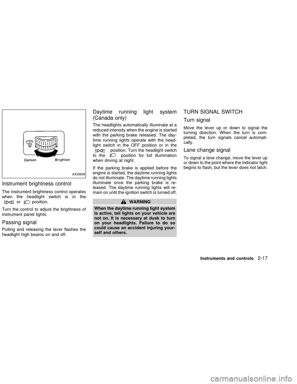
Instrument brightness control
The instrument brightness control operates
when the headlight switch is in the
orposition.
Turn the control to adjust the brightness of
instrument panel lights.
Passing signal
Pulling and releasing the lever flashes the
headlight high beams on and off.
Daytime running light system
(Canada only)
The headlights automatically illuminate at a
reduced intensity when the engine is started
with the parking brake released. The day-
time running lights operate with the head-
light switch in the OFF position or in the
position. Turn the headlight switch
to the
position for full illumination
when driving at night.
If the parking brake is applied before the
engine is started, the daytime running lights
do not illuminate. The daytime running lights
illuminate once the parking brake is re-
leased. The daytime running lights will re-
main on until the ignition switch is turned off.
WARNING
When the daytime running light system
is active, tail lights on your vehicle are
not on. It is necessary at dusk to turn
on your headlights. Failure to do so
could cause an accident injuring your-
self and others.
TURN SIGNAL SWITCH
Turn signal
Move the lever up or down to signal the
turning direction. When the turn is com-
pleted, the turn signals cancel automati-
cally.
Lane change signal
To signal a lane change, move the lever up
or down to the point where the indicator light
begins to flash, but the lever does not latch.
AIC0608
Instruments and controls2-17
ZX
Page 64 of 235

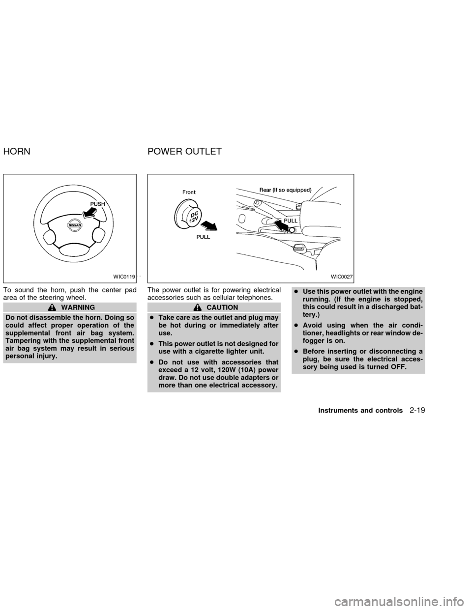
To sound the horn, push the center pad
area of the steering wheel.
WARNING
Do not disassemble the horn. Doing so
could affect proper operation of the
supplemental front air bag system.
Tampering with the supplemental front
air bag system may result in serious
personal injury.The power outlet is for powering electrical
accessories such as cellular telephones.CAUTION
cTake care as the outlet and plug may
be hot during or immediately after
use.
cThis power outlet is not designed for
use with a cigarette lighter unit.
cDo not use with accessories that
exceed a 12 volt, 120W (10A) power
draw. Do not use double adapters or
more than one electrical accessory.cUse this power outlet with the engine
running. (If the engine is stopped,
this could result in a discharged bat-
tery.)
cAvoid using when the air condi-
tioner, headlights or rear window de-
fogger is on.
cBefore inserting or disconnecting a
plug, be sure the electrical acces-
sory being used is turned OFF.
WIC0119WIC0027
HORN POWER OUTLET
Instruments and controls2-19
ZX
Page 72 of 235
The interior light has a three-position switch.
The interior light operates regardless of
ignition key position.
cWhen the switch is in the OFF position,
the interior light does not illuminate, re-
gardless of door position.
cWhen the switch is in the centerj
position, the interior light illuminates
when a door is opened.
cWhen the switch is in the ON position,
the interior light illuminates, regardless of
door position.
CAUTION
Do not use for extended periods of time
with the engine stopped. This could
result in a discharged battery.
To turn the map lights on, press the
switches. To turn them off, press the
switches again.
SIC0025LIC0045
INTERIOR LIGHT MAP LIGHTS (if so equipped)
Instruments and controls2-27
ZX
Page 82 of 235
1. Pull the hood lock release handles1
located below the driver side instrument
panel. The hood will spring up slightly.
2. Push the lever to the left
s2at the front
of the hood with your fingertips and raise
the hood.
3. Insert the support rod
s3into the slot
marked with the arrow on the underside
of the hood.
4. When closing the hood, return the sup-
port rod to its original position, lower the
hood to approximately 12 inches above
the latch and release it. This allows
proper engagement of the hood latch.
WARNING
cMake sure the hood is completely
closed and latched before driving.
Failure to do so could cause the
hood to fly open and result in an
accident.
cIf you see steam or smoke coming
from the engine compartment, to
avoid injury do not open the hood.
WPD0030WPD0020
HOOD
Pre-driving checks and adjustments3-9
ZX