2002 NISSAN PATROL relay
[x] Cancel search: relayPage 34 of 311
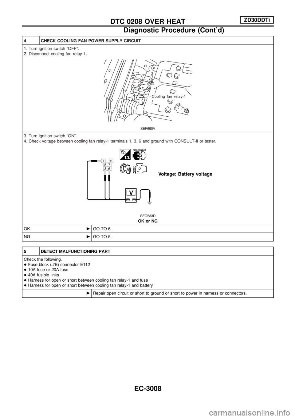
4 CHECK COOLING FAN POWER SUPPLY CIRCUIT
1. Turn ignition switch ªOFFº.
2. Disconnect cooling fan relay-1.
SEF690V
3. Turn ignition switch ªONº.
4. Check voltage between cooling fan relay-1 terminals 1, 3, 6 and ground with CONSULT-II or tester.
SEC533D
OK or NG
OKcGO TO 6.
NGcGO TO 5.
5 DETECT MALFUNCTIONING PART
Check the following.
+Fuse block (J/B) connector E112
+10A fuse or 20A fuse
+40A fusible links
+Harness for open or short between cooling fan relay-1 and fuse
+Harness for open or short between cooling fan relay-1 and battery
cRepair open circuit or short to ground or short to power in harness or connectors.
DTC 0208 OVER HEATZD30DDTi
Diagnostic Procedure (Cont'd)
EC-3008
Page 35 of 311
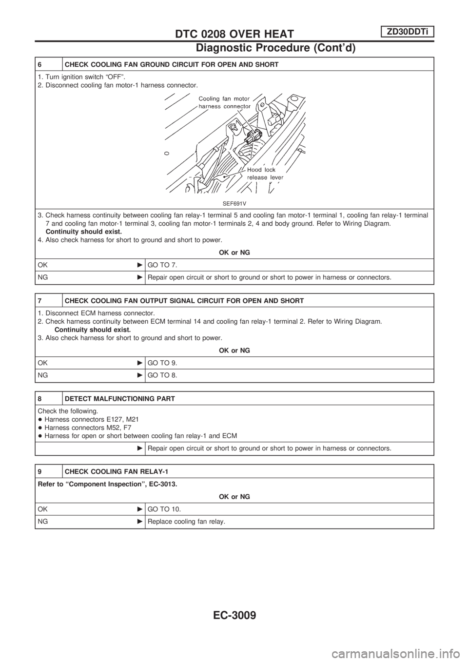
6 CHECK COOLING FAN GROUND CIRCUIT FOR OPEN AND SHORT
1. Turn ignition switch ªOFFº.
2. Disconnect cooling fan motor-1 harness connector.
SEF691V
3. Check harness continuity between cooling fan relay-1 terminal 5 and cooling fan motor-1 terminal 1, cooling fan relay-1 terminal
7 and cooling fan motor-1 terminal 3, cooling fan motor-1 terminals 2, 4 and body ground. Refer to Wiring Diagram.
Continuity should exist.
4. Also check harness for short to ground and short to power.
OK or NG
OKcGO TO 7.
NGcRepair open circuit or short to ground or short to power in harness or connectors.
7 CHECK COOLING FAN OUTPUT SIGNAL CIRCUIT FOR OPEN AND SHORT
1. Disconnect ECM harness connector.
2. Check harness continuity between ECM terminal 14 and cooling fan relay-1 terminal 2. Refer to Wiring Diagram.
Continuity should exist.
3. Also check harness for short to ground and short to power.
OK or NG
OKcGO TO 9.
NGcGO TO 8.
8 DETECT MALFUNCTIONING PART
Check the following.
+Harness connectors E127, M21
+Harness connectors M52, F7
+Harness for open or short between cooling fan relay-1 and ECM
cRepair open circuit or short to ground or short to power in harness or connectors.
9 CHECK COOLING FAN RELAY-1
Refer to ªComponent Inspectionº, EC-3013.
OK or NG
OKcGO TO 10.
NGcReplace cooling fan relay.
DTC 0208 OVER HEATZD30DDTi
Diagnostic Procedure (Cont'd)
EC-3009
Page 39 of 311
17 CHECK MAIN 12 CAUSES
If the cause cannot be isolated, go to ªMAIN 12 CAUSES OF OVERHEATINGº, EC-3014.
cINSPECTION END
Component Inspection
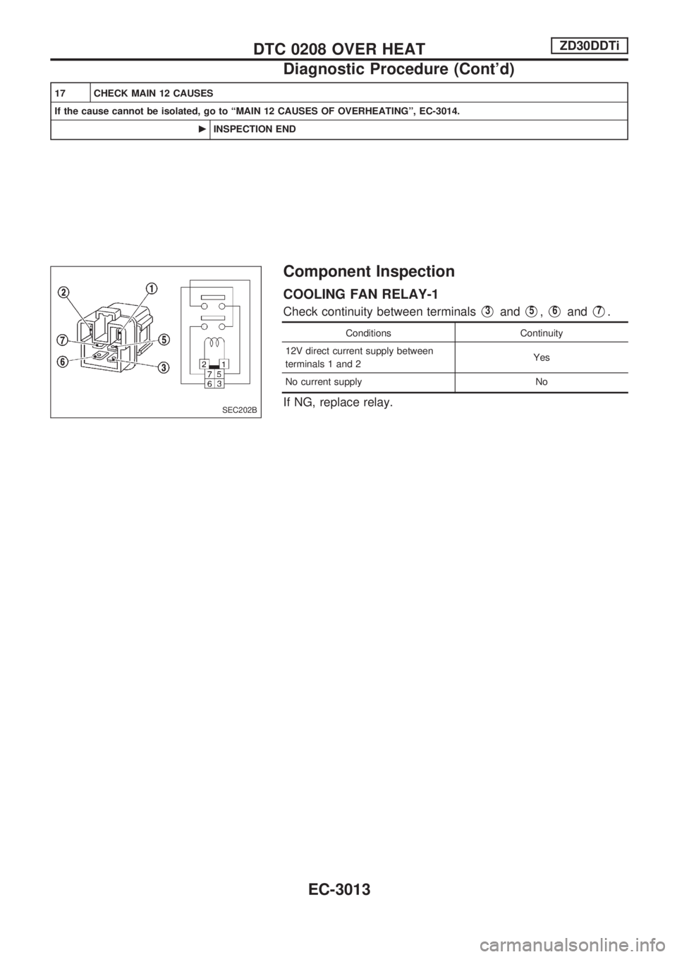
COOLING FAN RELAY-1
Check continuity between terminalsV3andV5,V6andV7.
Conditions Continuity
12V direct current supply between
terminals 1 and 2Yes
No current supply No
If NG, replace relay.SEC202B
DTC 0208 OVER HEATZD30DDTi
Diagnostic Procedure (Cont'd)
EC-3013
Page 225 of 311
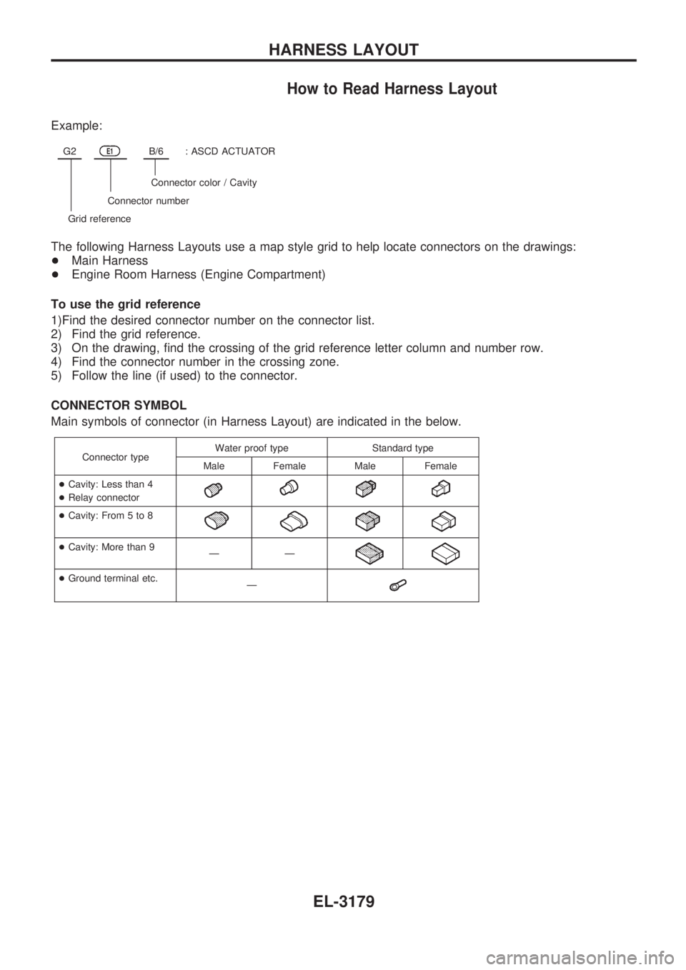
How to Read Harness Layout
Example:
G2E1B/6: ASCD ACTUATOR
Connector color / Cavity
Connector number
Grid reference
The following Harness Layouts use a map style grid to help locate connectors on the drawings:
+Main Harness
+Engine Room Harness (Engine Compartment)
To use the grid reference
1)Find the desired connector number on the connector list.
2) Find the grid reference.
3) On the drawing, find the crossing of the grid reference letter column and number row.
4) Find the connector number in the crossing zone.
5) Follow the line (if used) to the connector.
CONNECTOR SYMBOL
Main symbols of connector (in Harness Layout) are indicated in the below.
Connector typeWater proof type Standard type
Male Female Male Female
+Cavity: Less than 4
+Relay connector
+Cavity: From 5 to 8
+Cavity: More than 9
ÐÐ
+Ground terminal etc.
Ð
HARNESS LAYOUT
EL-3179
Page 256 of 311
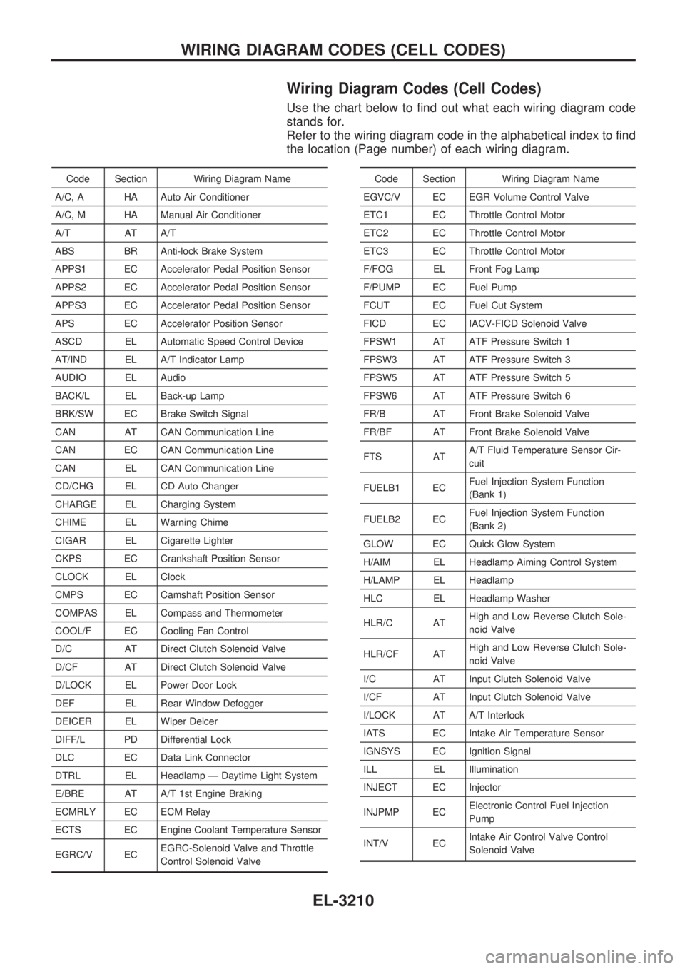
Wiring Diagram Codes (Cell Codes)
Use the chart below to find out what each wiring diagram code
stands for.
Refer to the wiring diagram code in the alphabetical index to find
the location (Page number) of each wiring diagram.
Code Section Wiring Diagram Name
A/C, A HA Auto Air Conditioner
A/C, M HA Manual Air Conditioner
A/T AT A/T
ABS BR Anti-lock Brake System
APPS1 EC Accelerator Pedal Position Sensor
APPS2 EC Accelerator Pedal Position Sensor
APPS3 EC Accelerator Pedal Position Sensor
APS EC Accelerator Position Sensor
ASCD EL Automatic Speed Control Device
AT/IND EL A/T Indicator Lamp
AUDIO EL Audio
BACK/L EL Back-up Lamp
BRK/SW EC Brake Switch Signal
CAN AT CAN Communication Line
CAN EC CAN Communication Line
CAN EL CAN Communication Line
CD/CHG EL CD Auto Changer
CHARGE EL Charging System
CHIME EL Warning Chime
CIGAR EL Cigarette Lighter
CKPS EC Crankshaft Position Sensor
CLOCK EL Clock
CMPS EC Camshaft Position Sensor
COMPAS EL Compass and Thermometer
COOL/F EC Cooling Fan Control
D/C AT Direct Clutch Solenoid Valve
D/CF AT Direct Clutch Solenoid Valve
D/LOCK EL Power Door Lock
DEF EL Rear Window Defogger
DEICER EL Wiper Deicer
DIFF/L PD Differential Lock
DLC EC Data Link Connector
DTRL EL Headlamp Ð Daytime Light System
E/BRE AT A/T 1st Engine Braking
ECMRLY EC ECM Relay
ECTS EC Engine Coolant Temperature Sensor
EGRC/V ECEGRC-Solenoid Valve and Throttle
Control Solenoid ValveCode Section Wiring Diagram Name
EGVC/V EC EGR Volume Control Valve
ETC1 EC Throttle Control Motor
ETC2 EC Throttle Control Motor
ETC3 EC Throttle Control Motor
F/FOG EL Front Fog Lamp
F/PUMP EC Fuel Pump
FCUT EC Fuel Cut System
FICD EC IACV-FICD Solenoid Valve
FPSW1 AT ATF Pressure Switch 1
FPSW3 AT ATF Pressure Switch 3
FPSW5 AT ATF Pressure Switch 5
FPSW6 AT ATF Pressure Switch 6
FR/B AT Front Brake Solenoid Valve
FR/BF AT Front Brake Solenoid Valve
FTS ATA/T Fluid Temperature Sensor Cir-
cuit
FUELB1 ECFuel Injection System Function
(Bank 1)
FUELB2 ECFuel Injection System Function
(Bank 2)
GLOW EC Quick Glow System
H/AIM EL Headlamp Aiming Control System
H/LAMP EL Headlamp
HLC EL Headlamp Washer
HLR/C ATHigh and Low Reverse Clutch Sole-
noid Valve
HLR/CF ATHigh and Low Reverse Clutch Sole-
noid Valve
I/C AT Input Clutch Solenoid Valve
I/CF AT Input Clutch Solenoid Valve
I/LOCK AT A/T Interlock
IATS EC Intake Air Temperature Sensor
IGNSYS EC Ignition Signal
ILL EL Illumination
INJECT EC Injector
INJPMP ECElectronic Control Fuel Injection
Pump
INT/V ECIntake Air Control Valve Control
Solenoid Valve
WIRING DIAGRAM CODES (CELL CODES)
EL-3210
Page 277 of 311
HEATER &
AIR CONDITIONER
SECTION
HA
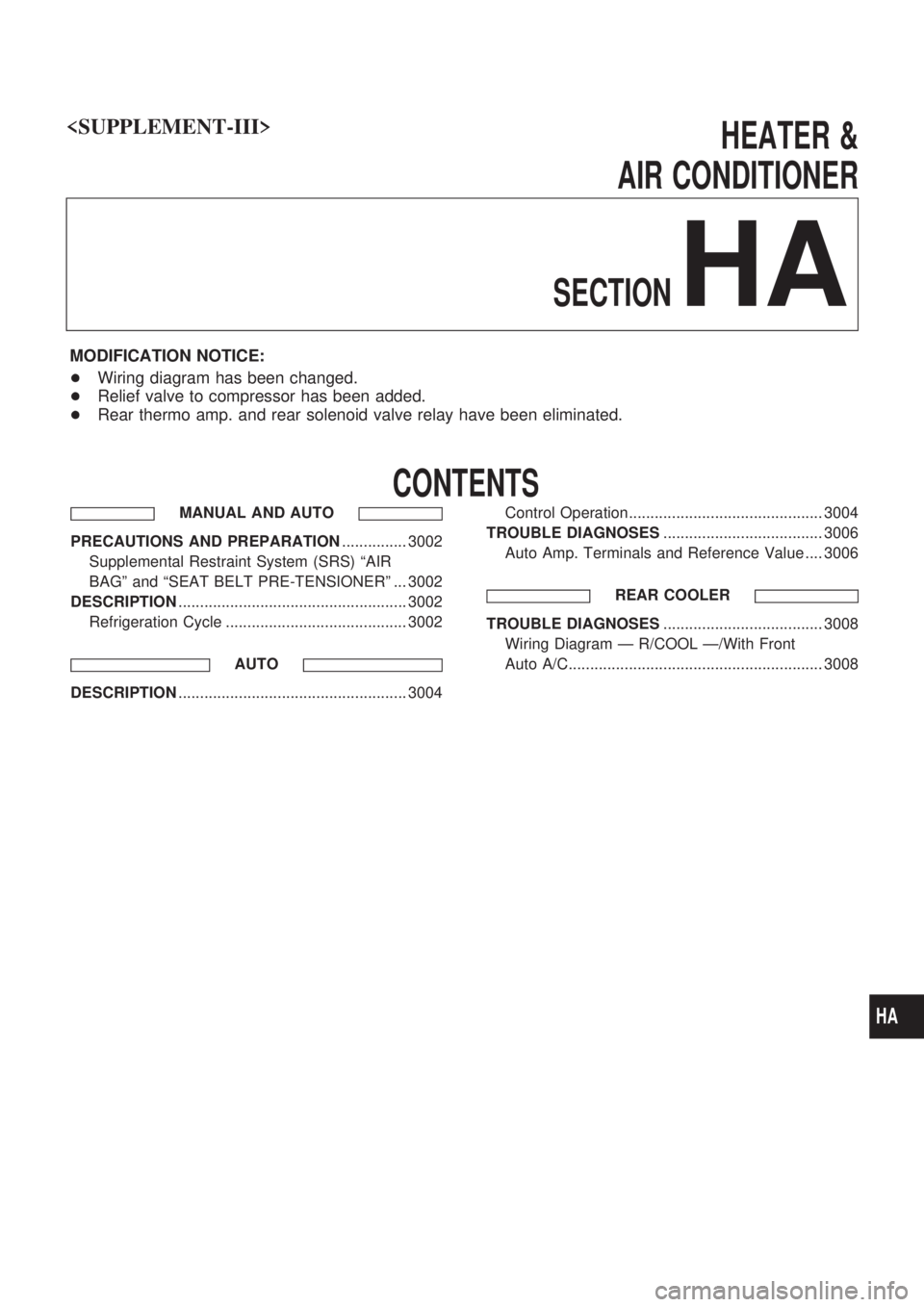
MODIFICATION NOTICE:
+Wiring diagram has been changed.
+Relief valve to compressor has been added.
+Rear thermo amp. and rear solenoid valve relay have been eliminated.
CONTENTS
MANUAL AND AUTO
PRECAUTIONS AND PREPARATION............... 3002
Supplemental Restraint System (SRS) ªAIR
BAGº and ªSEAT BELT PRE-TENSIONERº ... 3002
DESCRIPTION..................................................... 3002
Refrigeration Cycle .......................................... 3002
AUTO
DESCRIPTION..................................................... 3004Control Operation............................................. 3004
TROUBLE DIAGNOSES..................................... 3006
Auto Amp. Terminals and Reference Value .... 3006
REAR COOLER
TROUBLE DIAGNOSES..................................... 3008
Wiring Diagram Ð R/COOL Ð/With Front
Auto A/C........................................................... 3008
HA
Page 283 of 311
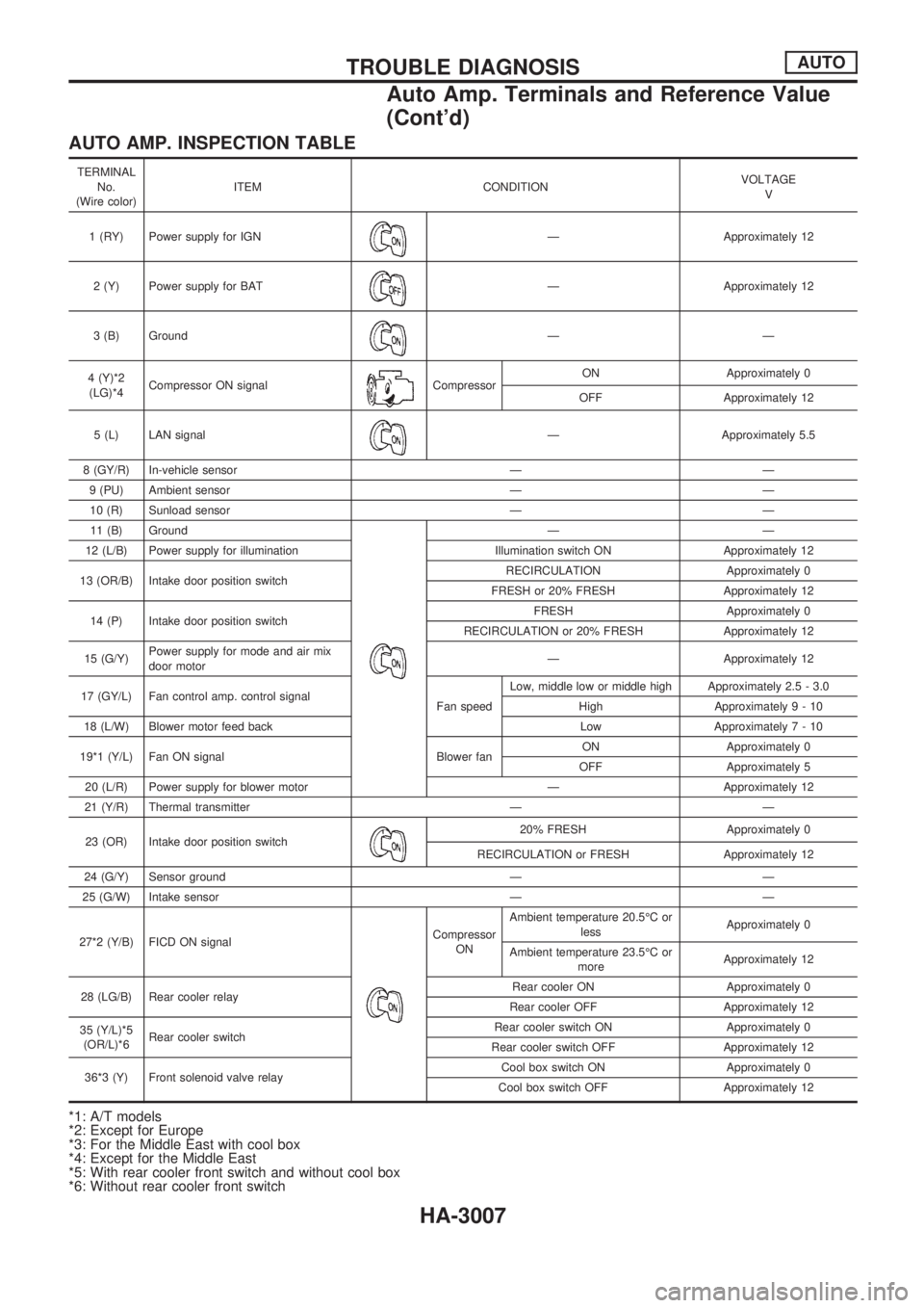
AUTO AMP. INSPECTION TABLE
TERMINAL
No.
(Wire color)ITEM CONDITIONVOLTAGE
V
1 (RY) Power supply for IGN
Ð Approximately 12
2 (Y) Power supply for BAT
Ð Approximately 12
3 (B) Ground
ÐÐ
4 (Y)*2
(LG)*4Compressor ON signal
CompressorON Approximately 0
OFF Approximately 12
5 (L) LAN signal
Ð Approximately 5.5
8 (GY/R) In-vehicle sensor Ð Ð
9 (PU) Ambient sensor Ð Ð
10 (R) Sunload sensor Ð Ð
11 (B) Ground
ÐÐ
12 (L/B) Power supply for illumination Illumination switch ON Approximately 12
13 (OR/B) Intake door position switchRECIRCULATION Approximately 0
FRESH or 20% FRESH Approximately 12
14 (P) Intake door position switchFRESH Approximately 0
RECIRCULATION or 20% FRESH Approximately 12
15 (G/Y)Power supply for mode and air mix
door motorÐ Approximately 12
17 (GY/L) Fan control amp. control signal
Fan speedLow, middle low or middle high Approximately 2.5 - 3.0
High Approximately9-10
18 (L/W) Blower motor feed back Low Approximately7-10
19*1 (Y/L) Fan ON signal Blower fanON Approximately 0
OFF Approximately 5
20 (L/R) Power supply for blower motor Ð Approximately 12
21 (Y/R) Thermal transmitter Ð Ð
23 (OR) Intake door position switch
20% FRESH Approximately 0
RECIRCULATION or FRESH Approximately 12
24 (G/Y) Sensor ground Ð Ð
25 (G/W) Intake sensor Ð Ð
27*2 (Y/B) FICD ON signal
Compressor
ONAmbient temperature 20.5ÉC or
lessApproximately 0
Ambient temperature 23.5ÉC or
moreApproximately 12
28 (LG/B) Rear cooler relayRear cooler ON Approximately 0
Rear cooler OFF Approximately 12
35 (Y/L)*5
(OR/L)*6Rear cooler switchRear cooler switch ON Approximately 0
Rear cooler switch OFF Approximately 12
36*3 (Y) Front solenoid valve relayCool box switch ON Approximately 0
Cool box switch OFF Approximately 12
*1: A/T models
*2: Except for Europe
*3: For the Middle East with cool box
*4: Except for the Middle East
*5: With rear cooler front switch and without cool box
*6: Without rear cooler front switch
TROUBLE DIAGNOSISAUTO
Auto Amp. Terminals and Reference Value
(Cont'd)
HA-3007