Page 1 of 311
Edition: October 2002
Release: November 2002 (01)
Publication No.: SM2E-Y61CE0E
Reference No.: 7711346700GENERAL INFORMATIONGI
MAINTENANCEMA
ENGINE MECHANICALEM
ENGINE LUBRICATION &
COOLING SYSTEMSLC
ENGINE CONTROL SYSTEMEC
ACCELERATOR CONTROL,
FUEL & EXHAUST SYSTEMFE
CLUTCHCL
MANUAL TRANSMISSIONMT
AUTOMATIC TRANSMISSIONAT
TRANSFERTF
PROPELLER SHAFT &
DIFFERENTIAL CARRIERPD
FRONT AXLE & FRONT SUSPENSIONFA
REAR AXLE & REAR SUSPENSIONRA
BRAKE SYSTEMBR
STEERING SYSTEMST
RESTRAINT SYSTEMRS
BODY & TRIMBT
HEATER & AIR CONDITIONERHA
ELECTRICAL SYSTEMEL
ALPHABETICAL INDEXIDX
PATROL GR
MODEL Y61 SERIES
NISSAN EUROPE S.A.S.
2002 NISSAN EUROPE S.A.S.
Produced in The Netherlands
Not to be reproduced in whole or in part
without the prior written permission of
Nissan Europe S.A.S., Paris, France.
QUICK REFERENCE INDEX
Page 2 of 311

FOREWORD
This manual contains maintenance and repair procedures for NISSAN
PATROL GR,modelY61 series.
In order to assure your safety and the efficient functioning of the vehicle,
this manual should be read thoroughly. It is especially important that the
PRECAUTIONS in the GI section be completely understood before starting
any repair task.
All information in this manual is based on the latest product information
at the time of publication. The right is reserved to make changes in speci-
®cations and methods at any time without notice.
IMPORTANT SAFETY NOTICE
The proper performance of service is essential for both the safety of the
technician and the efficient functioning of the vehicle.
The service methods in this Service Manual are described in such a man-
ner that the service may be performed safely and accurately.
Service varies with the procedures used, the skills of the technician and the
tools and parts available. Accordingly, anyone using service procedures,
tools or parts which are not speci®cally recommended by NISSAN must
®rst completely satisfy himself that neither his safety nor the vehicle's
safety will be jeopardized by the service method selected.
NISSAN EUROPE S.A.S.
Service Engineering SectionParis, France
Page 25 of 311

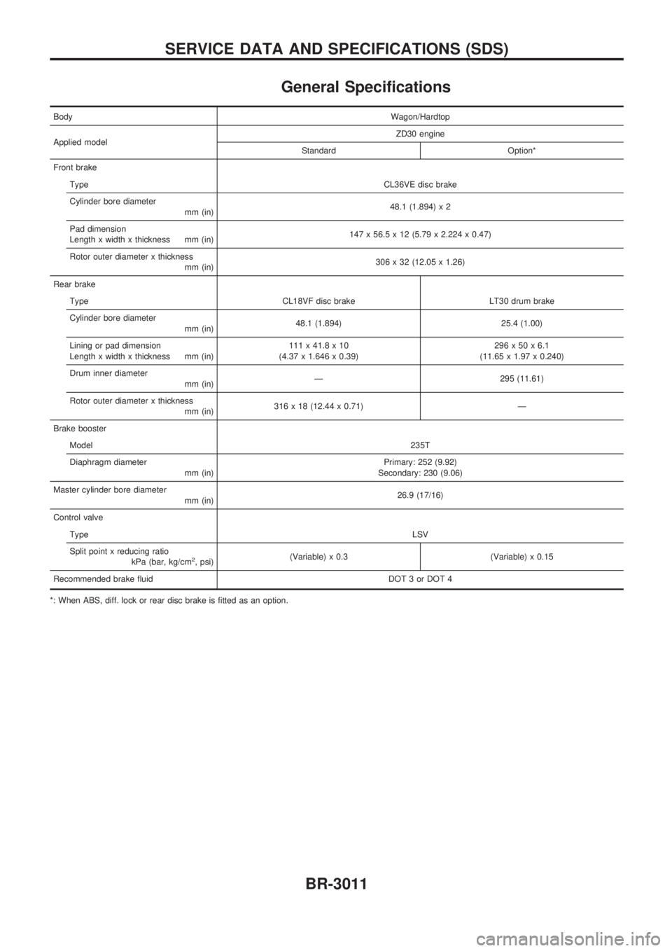
General Specifications
BodyWagon/Hardtop
Applied modelZD30 engine
Standard Option*
Front brake
TypeCL36VE disc brake
Cylinder bore diameter
mm (in)48.1 (1.894) x 2
Pad dimension
Length x width x thickness mm (in)147 x 56.5 x 12 (5.79 x 2.224 x 0.47)
Rotor outer diameter x thickness
mm (in)306 x 32 (12.05 x 1.26)
Rear brake
Type CL18VF disc brake LT30 drum brake
Cylinder bore diameter
mm (in)48.1 (1.894) 25.4 (1.00)
Lining or pad dimension
Length x width x thickness mm (in)111 x 41.8 x 10
(4.37 x 1.646 x 0.39)296x50x6.1
(11.65 x 1.97 x 0.240)
Drum inner diameter
mm (in)Ð 295 (11.61)
Rotor outer diameter x thickness
mm (in)316 x 18 (12.44 x 0.71) Ð
Brake booster
Model235T
Diaphragm diameter
mm (in)Primary: 252 (9.92)
Secondary: 230 (9.06)
Master cylinder bore diameter
mm (in)26.9 (17/16)
Control valve
TypeLSV
Split point x reducing ratio
kPa (bar, kg/cm
2, psi)(Variable) x 0.3 (Variable) x 0.15
Recommended brake fluid DOT 3 or DOT 4
*: When ABS, diff. lock or rear disc brake is fitted as an option.
SERVICE DATA AND SPECIFICATIONS (SDS)
BR-3011
Page 27 of 311

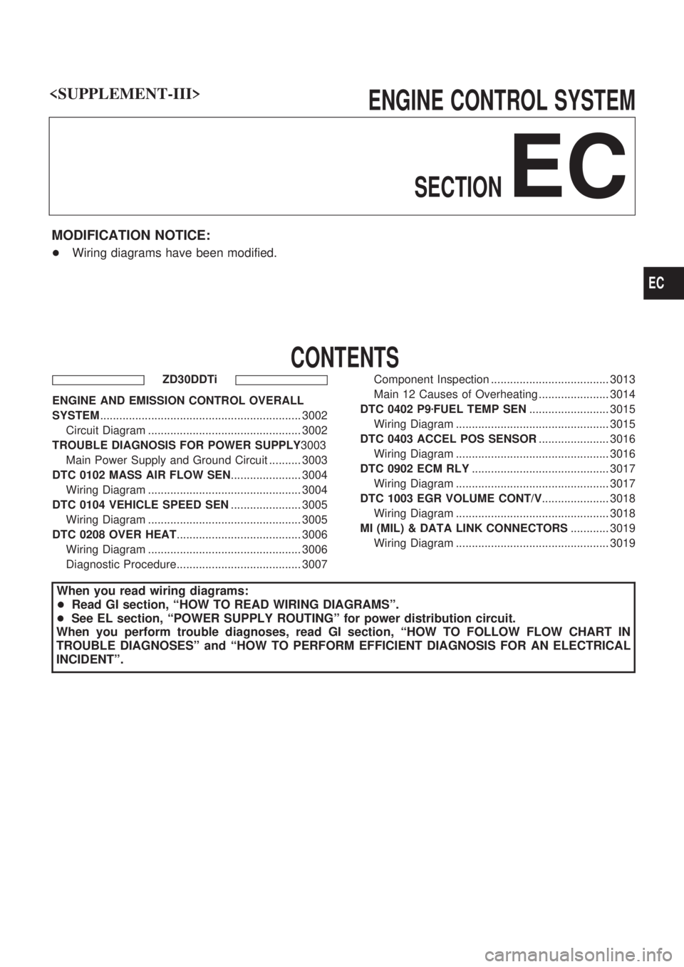
ENGINE CONTROL SYSTEM
SECTION
EC
MODIFICATION NOTICE:
+Wiring diagrams have been modified.
CONTENTS
ZD30DDTi
ENGINE AND EMISSION CONTROL OVERALL
SYSTEM............................................................... 3002
Circuit Diagram ................................................ 3002
TROUBLE DIAGNOSIS FOR POWER SUPPLY3003
Main Power Supply and Ground Circuit .......... 3003
DTC 0102 MASS AIR FLOW SEN...................... 3004
Wiring Diagram ................................................ 3004
DTC 0104 VEHICLE SPEED SEN...................... 3005
Wiring Diagram ................................................ 3005
DTC 0208 OVER HEAT....................................... 3006
Wiring Diagram ................................................ 3006
Diagnostic Procedure....................................... 3007Component Inspection ..................................... 3013
Main 12 Causes of Overheating ...................... 3014
DTC 0402 P9zFUEL TEMP SEN......................... 3015
Wiring Diagram ................................................ 3015
DTC 0403 ACCEL POS SENSOR...................... 3016
Wiring Diagram ................................................ 3016
DTC 0902 ECM RLY........................................... 3017
Wiring Diagram ................................................ 3017
DTC 1003 EGR VOLUME CONT/V..................... 3018
Wiring Diagram ................................................ 3018
MI (MIL) & DATA LINK CONNECTORS............ 3019
Wiring Diagram ................................................ 3019
When you read wiring diagrams:
+Read GI section, ªHOW TO READ WIRING DIAGRAMSº.
+See EL section, ªPOWER SUPPLY ROUTINGº for power distribution circuit.
When you perform trouble diagnoses, read GI section, ªHOW TO FOLLOW FLOW CHART IN
TROUBLE DIAGNOSESº and ªHOW TO PERFORM EFFICIENT DIAGNOSIS FOR AN ELECTRICAL
INCIDENTº.
EC
Page 28 of 311
Circuit Diagram
TEC395M
ENGINE AND EMISSION CONTROL OVERALL SYSTEMZD30DDTi
EC-3002
Page 33 of 311
Diagnostic Procedure
1 INSPECTION START
Do you have CONSULT-II?
Yes or No
YescGO TO 2.
NocGO TO 3.
2 CHECK COOLING FAN OPERATION
With CONSULT-II
1. Turn ignition switch ªONº.
2. Perform ªCOOLING FANº in ªACTIVE TESTº mode with CONSULT-II.
SEF646X
3. Make sure that cooling fan-1 operates.
OK or NG
OKcGO TO 12.
NGcGO TO 4.
3 CHECK COOLING FAN OPERATION
Without CONSULT-II
1. Turn ignition switch ªOFFº.
2. Disconnect engine coolant temperature sensor harness connector.
3. Connect 150Wresistor to engine coolant temperature sensor harness connector.
4. Restart engine and make sure that cooling fan operates.
MEC475B
OK or NG
OKcGO TO 12.
NGcGO TO 4.
DTC 0208 OVER HEATZD30DDTi
EC-3007
Page 38 of 311
15 CHECK THERMOSTAT
1. Remove thermostat.
2. Check valve seating condition at normal room temperatures.
It should seat tightly.
3. Check valve opening temperature and valve lift.
SLC343
Valve opening temperature:
82ÉC (180ÉF) [standard] (Models for cold areas)
76.5ÉC (170ÉF) [standard] (Models for except cold areas)
Valve lift:
More than 10 mm/95ÉC (0.394 in/203ÉF)
4. Check if valve is closed at 5ÉC (9ÉF) below valve opening temperature. For details, refer to LC section, ªThermostatº.
OK or NG
OKcGO TO 16.
NGcReplace thermostat.
16 CHECK ENGINE COOLANT TEMPERATURE SENSOR
1. Remove engine coolant temperature sensor.
2. Check resistance between engine coolant temperature sensor terminals 1 and 2 as shown in the figure.
SEF304X
OK or NG
OKcGO TO 17.
NGcReplace engine coolant temperature sensor.
DTC 0208 OVER HEATZD30DDTi
Diagnostic Procedure (Cont'd)
EC-3012
Page 40 of 311

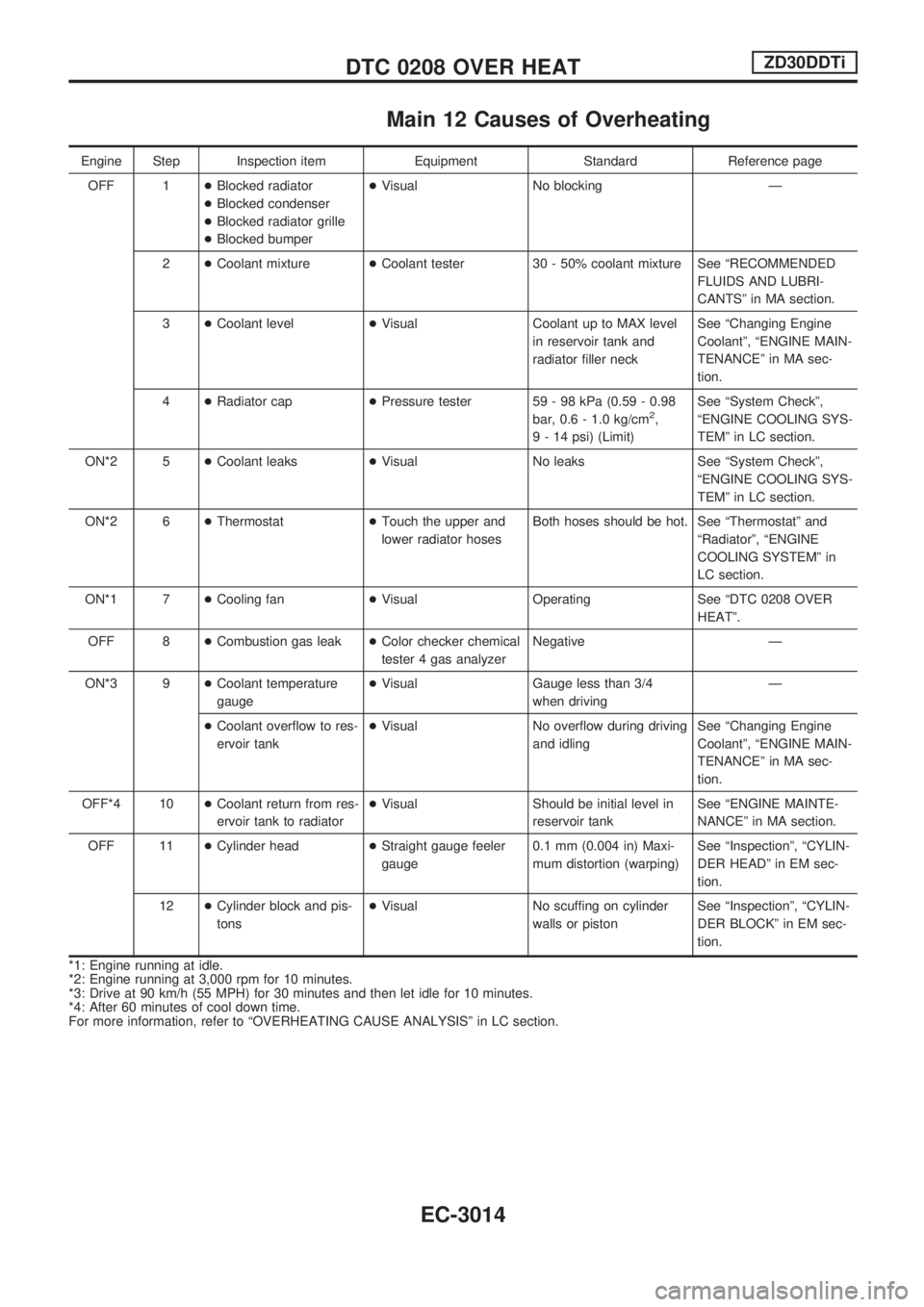
Main 12 Causes of Overheating
Engine Step Inspection item Equipment Standard Reference page
OFF 1+Blocked radiator
+Blocked condenser
+Blocked radiator grille
+Blocked bumper+Visual No blocking Ð
2+Coolant mixture+Coolant tester 30 - 50% coolant mixture See ªRECOMMENDED
FLUIDS AND LUBRI-
CANTSº in MA section.
3+Coolant level+Visual Coolant up to MAX level
in reservoir tank and
radiator filler neckSee ªChanging Engine
Coolantº, ªENGINE MAIN-
TENANCEº in MA sec-
tion.
4+Radiator cap+Pressure tester 59 - 98 kPa (0.59 - 0.98
bar, 0.6 - 1.0 kg/cm
2,
9 - 14 psi) (Limit)See ªSystem Checkº,
ªENGINE COOLING SYS-
TEMº in LC section.
ON*2 5+Coolant leaks+Visual No leaks See ªSystem Checkº,
ªENGINE COOLING SYS-
TEMº in LC section.
ON*2 6+Thermostat+Touch the upper and
lower radiator hosesBoth hoses should be hot. See ªThermostatº and
ªRadiatorº, ªENGINE
COOLING SYSTEMº in
LC section.
ON*1 7+Cooling fan+Visual Operating See ªDTC 0208 OVER
HEATº.
OFF 8+Combustion gas leak+Color checker chemical
tester 4 gas analyzerNegative Ð
ON*3 9+Coolant temperature
gauge+Visual Gauge less than 3/4
when drivingÐ
+Coolant overflow to res-
ervoir tank+Visual No overflow during driving
and idlingSee ªChanging Engine
Coolantº, ªENGINE MAIN-
TENANCEº in MA sec-
tion.
OFF*4 10+Coolant return from res-
ervoir tank to radiator+Visual Should be initial level in
reservoir tankSee ªENGINE MAINTE-
NANCEº in MA section.
OFF 11+Cylinder head+Straight gauge feeler
gauge0.1 mm (0.004 in) Maxi-
mum distortion (warping)See ªInspectionº, ªCYLIN-
DER HEADº in EM sec-
tion.
12+Cylinder block and pis-
tons+Visual No scuffing on cylinder
walls or pistonSee ªInspectionº, ªCYLIN-
DER BLOCKº in EM sec-
tion.
*1: Engine running at idle.
*2: Engine running at 3,000 rpm for 10 minutes.
*3: Drive at 90 km/h (55 MPH) for 30 minutes and then let idle for 10 minutes.
*4: After 60 minutes of cool down time.
For more information, refer to ªOVERHEATING CAUSE ANALYSISº in LC section.
DTC 0208 OVER HEATZD30DDTi
EC-3014