2002 NISSAN PATROL engine
[x] Cancel search: enginePage 260 of 311
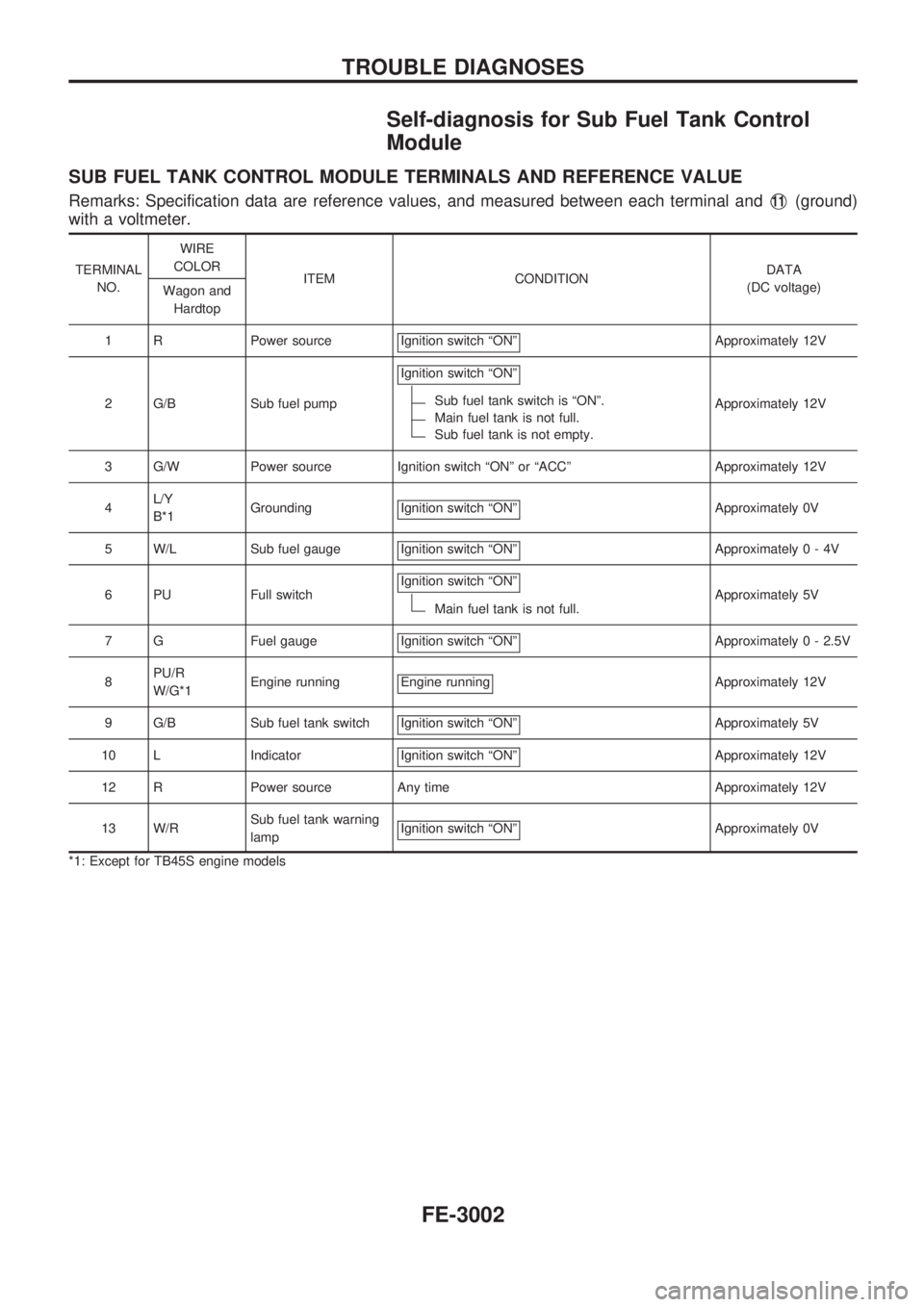
Self-diagnosis for Sub Fuel Tank Control
Module
SUB FUEL TANK CONTROL MODULE TERMINALS AND REFERENCE VALUE
Remarks: Specification data are reference values, and measured between each terminal andV11(ground)
with a voltmeter.
TERMINAL
NO.WIRE
COLOR
ITEM CONDITIONDATA
(DC voltage)
Wagon and
Hardtop
1 R Power source Ignition switch ªONº
Approximately 12V
2 G/B Sub fuel pumpIgnition switch ªONº
Sub fuel tank switch is ªONº.
Main fuel tank is not full.
Sub fuel tank is not empty.Approximately 12V
3 G/W Power source Ignition switch ªONº or ªACCº Approximately 12V
4L/Y
B*1Grounding Ignition switch ªONº
Approximately 0V
5 W/L Sub fuel gauge Ignition switch ªONº
Approximately0-4V
6 PU Full switchIgnition switch ªONº
Main fuel tank is not full.Approximately 5V
7 G Fuel gauge Ignition switch ªONº
Approximately 0 - 2.5V
8PU/R
W/G*1Engine running Engine running
Approximately 12V
9 G/B Sub fuel tank switch Ignition switch ªONº
Approximately 5V
10 L Indicator Ignition switch ªONº
Approximately 12V
12 R Power source Any time Approximately 12V
13 W/RSub fuel tank warning
lampIgnition switch ªONº
Approximately 0V
*1: Except for TB45S engine models
TROUBLE DIAGNOSES
FE-3002
Page 270 of 311
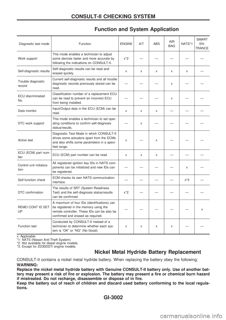
Function and System Application
Diagnostic test mode Function ENGINE A/T ABSAIR
BAGNATS*1SMART
EN-
TRANCE
Work supportThis mode enables a technician to adjust
some devices faster and more accurate by
following the indications on CONSULT-II.x*2ÐÐÐÐÐ
Self-diagnostic resultsSelf-diagnostic results can be read and
erased quickly.xxxxxÐ
Trouble diagnostic
recordCurrent self-diagnostic results and all trouble
diagnostic records previously stored can be
read.ÐÐÐxÐÐ
ECU discriminated
No.Classification number of a replacement ECU
can be read to prevent an incorrect ECU
from being installed.ÐÐÐxÐÐ
Data monitorInput/Output data in the ECU (ECM) can be
read.xxxÐÐÐ
DTC work supportThis mode enables a technician to set oper-
ating conditions to confirm self-diagnosis
status/results.Ð x ÐÐÐÐ
Active testDiagnostic Test Mode in which CONSULT-II
drives some actuators apart from the ECMs
and also shifts some parameters in a speci-
fied range.xÐxÐÐÐ
ECU (ECM) part num-
berECU (ECM) part number can be read. x x x Ð Ð Ð
Control unit initializa-
tionAll registered ignition key IDs in NATS com-
ponents can be initialized and new IDs can
be registered.ÐÐÐÐ x Ð
Self-function checkECM checks its own NATS communication
interface.ÐÐÐÐx*3Ð
DTC confirmationThe results of SRT (System Readiness
Test) and the self-diagnosis status/results
can be confirmed.x*2ÐÐÐÐÐ
REMO CONT ID SET
UPA maximum of four IDs (identifications) can
be registered in the memory using the
remote controller. These IDs can be also be
confirmed and erased as required.ÐÐÐÐÐ x
Function testConducted by CONSULT-II instead of a
technician to determine whether each sys-
tem is ªOKº or ªNGº (No Good).xxxxÐÐ
x: Applicable
*1: NATS (Nissan Anti-Theft System)
*2: Not available for diesel engine models.
*3: Except for ZD30DDTi engine models.
Nickel Metal Hydride Battery Replacement
CONSULT-II contains a nickel metal hydride battery. When replacing the battery obey the following:
WARNING:
Replace the nickel metal hydride battery with Genuine CONSULT-II battery only. Use of another bat-
tery may present a risk of fire or explosion. The battery may present a fire or chemical burn hazard
if mistreated. Do not recharge, disassemble or dispose of in fire.
Keep the battery out of reach of children and discard used battery conforming to the local regula-
tions.
CONSULT-II CHECKING SYSTEM
GI-3002
Page 272 of 311
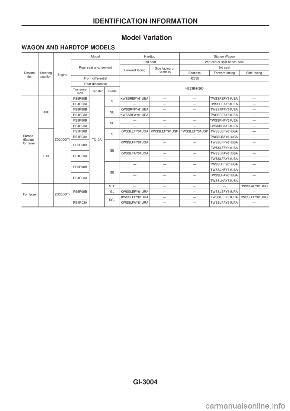
Model Variation
WAGON AND HARDTOP MODELS
Destina-
tionSteering
positionEngineModel Hardtop Station Wagon
Rear seat arrangement2nd seat 2nd center split bench seat
Forward facingSide facing or
Seatless3rd seat
Seatless Forward facing Side facing
Front differential H233B
Rear differential
H233B/H260
Transmis-
sionTransfer Grade
Europe
(Except
for Israel)RHD
ZD30DDTiFS5R50B
TX12ASKWSSREFY61UEA Ð Ð TWSSREFY61UEA Ð
RE4R03A Ð Ð Ð TWSSREAY61UEA Ð
FS5R50B
SEKWSSRFFY61UEA Ð Ð TWSSRFFY61UEA Ð
RE4R03A KWSSRFAY61UEA Ð Ð TWSSRFAY61UEA Ð
FS5R50B
SEÐ Ð Ð TWSSRHFY61UEA Ð
RE4R03A Ð Ð Ð TWSSRHAY61UEA Ð
LHDFS5R50B
SKWSSLEFY61UGA KWSSLEFY61USP TWSSLEFY61USP TWSSLEFY61UGA Ð
RE4R03A Ð Ð Ð TWSSLEAY61UGA Ð
FS5R50B
SEKWSSLFFY61UGA Ð Ð TWSSLFFY61UGA Ð
Ð Ð Ð TWSSLFFY61USA Ð
RE4R03AKWSSLFAY61UGA Ð Ð TWSSLFAY61UGA Ð
Ð Ð Ð TWSSLFAY61USA Ð
FS5R50B
SEÐ Ð Ð TWSSLHFY61UGA Ð
Ð Ð Ð TWSSLHFY61USA Ð
RE4R03AÐ Ð Ð TWSSLHAY61UGA Ð
Ð Ð Ð TWSSLHAY61USA Ð
For Israel ZD30DDTiFS5R05BSTDÐÐÐÐTWSSLAFY61URQ
GL KWSSLEFY61URA Ð Ð TWSSLEFY61URA Ð
SGLKWSSLFFY61URA Ð Ð TWSSLFFY61URA TWSSLFFY61URQ
RE4R03A KWSSLFAY61URA Ð Ð TWSSLFAY61URA Ð
IDENTIFICATION INFORMATION
GI-3004
Page 273 of 311
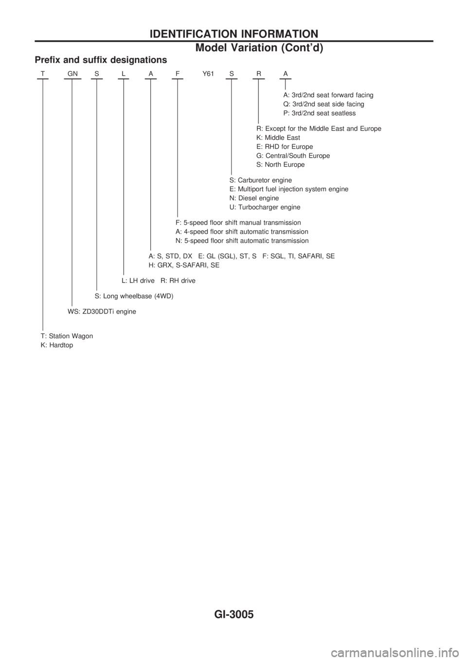
Prefix and suffix designations
TGNSLAFY61 SRA
A: 3rd/2nd seat forward facing
Q: 3rd/2nd seat side facing
P: 3rd/2nd seat seatless
R: Except for the Middle East and Europe
K: Middle East
E: RHD for Europe
G: Central/South Europe
S: North Europe
S: Carburetor engine
E: Multiport fuel injection system engine
N: Diesel engine
U: Turbocharger engine
F: 5-speed floor shift manual transmission
A: 4-speed floor shift automatic transmission
N: 5-speed floor shift automatic transmission
A: S, STD, DX E: GL (SGL), ST, S F: SGL, TI, SAFARI, SE
H: GRX, S-SAFARI, SE
L: LH drive R: RH drive
S: Long wheelbase (4WD)
WS: ZD30DDTi engine
T: Station Wagon
K: Hardtop
IDENTIFICATION INFORMATION
Model Variation (Cont'd)
GI-3005
Page 274 of 311
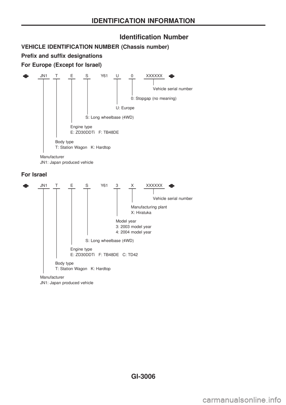
Identification Number
VEHICLE IDENTIFICATION NUMBER (Chassis number)
Prefix and suffix designations
For Europe (Except for Israel)
JN1TESY61 U0XXXXXX
Vehicle serial number
0: Stopgap (no meaning)
U: Europe
S: Long wheelbase (4WD)
Engine type
E: ZD30DDTi F: TB48DE
Body type
T: Station Wagon K: Hardtop
Manufacturer
JN1: Japan produced vehicle
For Israel
JN1TESY61 3XXXXXXX
Vehicle serial number
Manufacturing plant
X: Hiratuka
Model year
3: 2003 model year
4: 2004 model year
S: Long wheelbase (4WD)
Engine type
E: ZD30DDTi F: TB48DE C: TD42
Body type
T: Station Wagon K: Hardtop
Manufacturer
JN1: Japan produced vehicle
IDENTIFICATION INFORMATION
GI-3006
Page 280 of 311
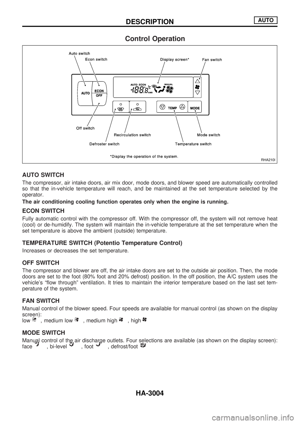
Control Operation
AUTO SWITCH
The compressor, air intake doors, air mix door, mode doors, and blower speed are automatically controlled
so that the in-vehicle temperature will reach, and be maintained at the set temperature selected by the
operator.
The air conditioning cooling function operates only when the engine is running.
ECON SWITCH
Fully automatic control with the compressor off. With the compressor off, the system will not remove heat
(cool) or de-humidify. The system will maintain the in-vehicle temperature at the set temperature when the
set temperature is above the ambient (outside) temperature.
TEMPERATURE SWITCH (Potentio Temperature Control)
Increases or decreases the set temperature.
OFF SWITCH
The compressor and blower are off, the air intake doors are set to the outside air position. Then, the mode
doors are set to the foot (80% foot and 20% defrost) position. In the off position, the A/C system uses the
vehicle's ªflow throughº ventilation. It tries to maintain the interior temperature based on the last set tem-
perature of the system.
FAN SWITCH
Manual control of the blower speed. Four speeds are available for manual control (as shown on the display
screen):
low
, medium low, medium high, high
MODE SWITCH
Manual control of the air discharge outlets. Four selections are available (as shown on the display screen):
face
, bi-level, foot, defrost/foot
RHA210I
DESCRIPTIONAUTO
HA-3004
Page 288 of 311
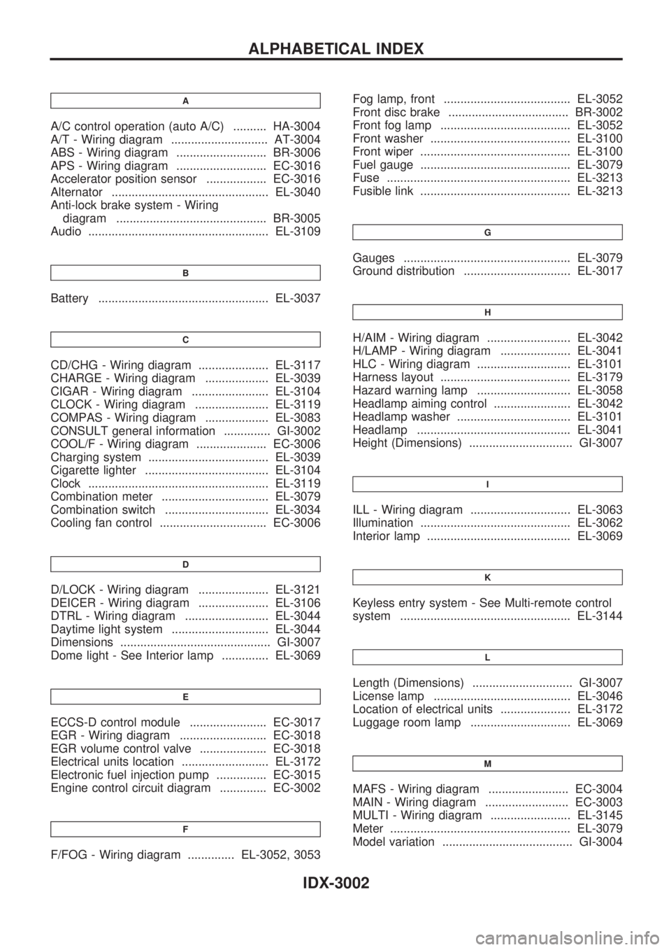
A
A/C control operation (auto A/C) .......... HA-3004
A/T - Wiring diagram ............................. AT-3004
ABS - Wiring diagram ........................... BR-3006
APS - Wiring diagram ........................... EC-3016
Accelerator position sensor .................. EC-3016
Alternator ............................................... EL-3040
Anti-lock brake system - Wiring
diagram ............................................. BR-3005
Audio ...................................................... EL-3109
B
Battery ................................................... EL-3037
C
CD/CHG - Wiring diagram ..................... EL-3117
CHARGE - Wiring diagram ................... EL-3039
CIGAR - Wiring diagram ....................... EL-3104
CLOCK - Wiring diagram ...................... EL-3119
COMPAS - Wiring diagram ................... EL-3083
CONSULT general information .............. GI-3002
COOL/F - Wiring diagram ..................... EC-3006
Charging system .................................... EL-3039
Cigarette lighter ..................................... EL-3104
Clock ...................................................... EL-3119
Combination meter ................................ EL-3079
Combination switch ............................... EL-3034
Cooling fan control ................................ EC-3006
D
D/LOCK - Wiring diagram ..................... EL-3121
DEICER - Wiring diagram ..................... EL-3106
DTRL - Wiring diagram ......................... EL-3044
Daytime light system ............................. EL-3044
Dimensions ............................................. GI-3007
Dome light - See Interior lamp .............. EL-3069
E
ECCS-D control module ....................... EC-3017
EGR - Wiring diagram .......................... EC-3018
EGR volume control valve .................... EC-3018
Electrical units location .......................... EL-3172
Electronic fuel injection pump ............... EC-3015
Engine control circuit diagram .............. EC-3002
F
F/FOG - Wiring diagram .............. EL-3052, 3053Fog lamp, front ...................................... EL-3052
Front disc brake .................................... BR-3002
Front fog lamp ....................................... EL-3052
Front washer .......................................... EL-3100
Front wiper ............................................. EL-3100
Fuel gauge ............................................. EL-3079
Fuse ....................................................... EL-3213
Fusible link ............................................. EL-3213
G
Gauges .................................................. EL-3079
Ground distribution ................................ EL-3017
H
H/AIM - Wiring diagram ......................... EL-3042
H/LAMP - Wiring diagram ..................... EL-3041
HLC - Wiring diagram ............................ EL-3101
Harness layout ....................................... EL-3179
Hazard warning lamp ............................ EL-3058
Headlamp aiming control ....................... EL-3042
Headlamp washer .................................. EL-3101
Headlamp .............................................. EL-3041
Height (Dimensions) ............................... GI-3007
I
ILL - Wiring diagram .............................. EL-3063
Illumination ............................................. EL-3062
Interior lamp ........................................... EL-3069
K
Keyless entry system - See Multi-remote control
system ................................................... EL-3144
L
Length (Dimensions) .............................. GI-3007
License lamp ......................................... EL-3046
Location of electrical units ..................... EL-3172
Luggage room lamp .............................. EL-3069
M
MAFS - Wiring diagram ........................ EC-3004
MAIN - Wiring diagram ......................... EC-3003
MULTI - Wiring diagram ........................ EL-3145
Meter ...................................................... EL-3079
Model variation ....................................... GI-3004
ALPHABETICAL INDEX
IDX-3002
Page 293 of 311
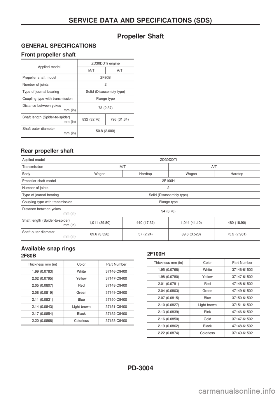
Propeller Shaft
GENERAL SPECIFICATIONS
Front propeller shaft
Applied modelZD30DDTi engine
M/T A/T
Propeller shaft model 2F80B
Number of joints 2
Type of journal bearing Solid (Disassembly type)
Coupling type with transmission Flange type
Distance between yokes
mm (in)73 (2.87)
Shaft length (Spider-to-spider)
mm (in)832 (32.76) 796 (31.34)
Shaft outer diameter
mm (in)50.8 (2.000)
Rear propeller shaft
Applied modelZD30DDTi
Transmission M/T A/T
Body Wagon Hardtop Wagon Hardtop
Propeller shaft model 2F100H
Number of joints2
Type of journal bearing Solid (Disassembly type)
Coupling type with transmission Flange type
Distance between yokes
mm (in)94 (3.70)
Shaft length (Spider-to-spider)
mm (in)1,011 (39.80) 440 (17.32) 1,044 (41.10) 480 (18.90)
Shaft outer diameter
mm (in)89.6 (3.528) 57 (2.24) 89.6 (3.528) 75.2 (2.961)
Available snap rings
2F80B
Thickness mm (in) Color Part Number
1.99 (0.0783) White 37146-C9400
2.02 (0.0795) Yellow 37147-C9400
2.05 (0.0807) Red 37148-C9400
2.08 (0.0819) Green 37149-C9400
2.11 (0.0831) Blue 37150-C9400
2.14 (0.0843) Light brown 37151-C9400
2.17 (0.0854) Black 37152-C9400
2.20 (0.0866) Colorless 37153-C9400
2F100H
Thickness mm (in) Color Part Number
1.95 (0.0768) White 37146-61502
1.98 (0.0780) Yellow 37147-61502
2.01 (0.0791) Red 47148-61502
2.04 (0.0803) Green 47149-61502
2.07 (0.0815) Blue 37150-61502
2.10 (0.0827) Light brown 37151-61502
2.13 (0.0839) Pink 47146-61502
2.16 (0.0850) Gold 37147-61502
2.19 (0.0862) Black 47148-61502
2.22 (0.0874) Colorless 37149-61502
SERVICE DATA AND SPECIFICATIONS (SDS)
PD-3004