2002 NISSAN PATROL air condition
[x] Cancel search: air conditionPage 1 of 311
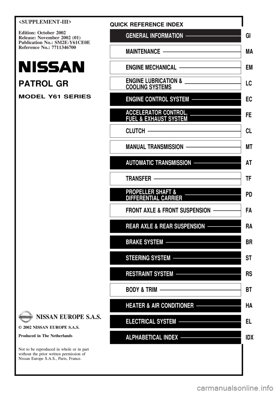
Edition: October 2002
Release: November 2002 (01)
Publication No.: SM2E-Y61CE0E
Reference No.: 7711346700GENERAL INFORMATIONGI
MAINTENANCEMA
ENGINE MECHANICALEM
ENGINE LUBRICATION &
COOLING SYSTEMSLC
ENGINE CONTROL SYSTEMEC
ACCELERATOR CONTROL,
FUEL & EXHAUST SYSTEMFE
CLUTCHCL
MANUAL TRANSMISSIONMT
AUTOMATIC TRANSMISSIONAT
TRANSFERTF
PROPELLER SHAFT &
DIFFERENTIAL CARRIERPD
FRONT AXLE & FRONT SUSPENSIONFA
REAR AXLE & REAR SUSPENSIONRA
BRAKE SYSTEMBR
STEERING SYSTEMST
RESTRAINT SYSTEMRS
BODY & TRIMBT
HEATER & AIR CONDITIONERHA
ELECTRICAL SYSTEMEL
ALPHABETICAL INDEXIDX
PATROL GR
MODEL Y61 SERIES
NISSAN EUROPE S.A.S.
2002 NISSAN EUROPE S.A.S.
Produced in The Netherlands
Not to be reproduced in whole or in part
without the prior written permission of
Nissan Europe S.A.S., Paris, France.
QUICK REFERENCE INDEX
Page 256 of 311
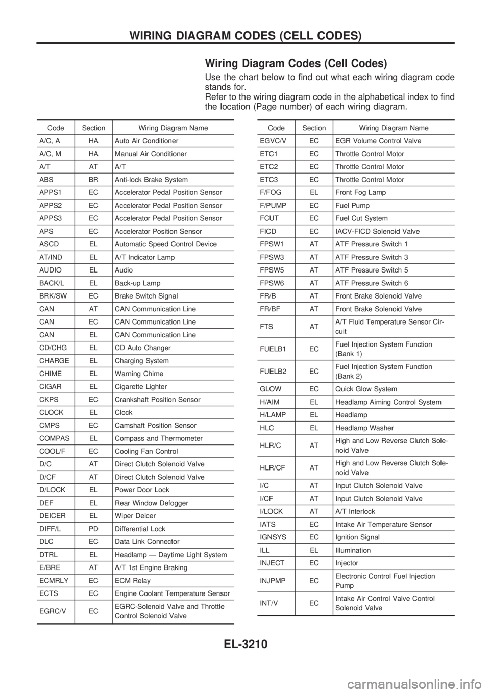
Wiring Diagram Codes (Cell Codes)
Use the chart below to find out what each wiring diagram code
stands for.
Refer to the wiring diagram code in the alphabetical index to find
the location (Page number) of each wiring diagram.
Code Section Wiring Diagram Name
A/C, A HA Auto Air Conditioner
A/C, M HA Manual Air Conditioner
A/T AT A/T
ABS BR Anti-lock Brake System
APPS1 EC Accelerator Pedal Position Sensor
APPS2 EC Accelerator Pedal Position Sensor
APPS3 EC Accelerator Pedal Position Sensor
APS EC Accelerator Position Sensor
ASCD EL Automatic Speed Control Device
AT/IND EL A/T Indicator Lamp
AUDIO EL Audio
BACK/L EL Back-up Lamp
BRK/SW EC Brake Switch Signal
CAN AT CAN Communication Line
CAN EC CAN Communication Line
CAN EL CAN Communication Line
CD/CHG EL CD Auto Changer
CHARGE EL Charging System
CHIME EL Warning Chime
CIGAR EL Cigarette Lighter
CKPS EC Crankshaft Position Sensor
CLOCK EL Clock
CMPS EC Camshaft Position Sensor
COMPAS EL Compass and Thermometer
COOL/F EC Cooling Fan Control
D/C AT Direct Clutch Solenoid Valve
D/CF AT Direct Clutch Solenoid Valve
D/LOCK EL Power Door Lock
DEF EL Rear Window Defogger
DEICER EL Wiper Deicer
DIFF/L PD Differential Lock
DLC EC Data Link Connector
DTRL EL Headlamp Ð Daytime Light System
E/BRE AT A/T 1st Engine Braking
ECMRLY EC ECM Relay
ECTS EC Engine Coolant Temperature Sensor
EGRC/V ECEGRC-Solenoid Valve and Throttle
Control Solenoid ValveCode Section Wiring Diagram Name
EGVC/V EC EGR Volume Control Valve
ETC1 EC Throttle Control Motor
ETC2 EC Throttle Control Motor
ETC3 EC Throttle Control Motor
F/FOG EL Front Fog Lamp
F/PUMP EC Fuel Pump
FCUT EC Fuel Cut System
FICD EC IACV-FICD Solenoid Valve
FPSW1 AT ATF Pressure Switch 1
FPSW3 AT ATF Pressure Switch 3
FPSW5 AT ATF Pressure Switch 5
FPSW6 AT ATF Pressure Switch 6
FR/B AT Front Brake Solenoid Valve
FR/BF AT Front Brake Solenoid Valve
FTS ATA/T Fluid Temperature Sensor Cir-
cuit
FUELB1 ECFuel Injection System Function
(Bank 1)
FUELB2 ECFuel Injection System Function
(Bank 2)
GLOW EC Quick Glow System
H/AIM EL Headlamp Aiming Control System
H/LAMP EL Headlamp
HLC EL Headlamp Washer
HLR/C ATHigh and Low Reverse Clutch Sole-
noid Valve
HLR/CF ATHigh and Low Reverse Clutch Sole-
noid Valve
I/C AT Input Clutch Solenoid Valve
I/CF AT Input Clutch Solenoid Valve
I/LOCK AT A/T Interlock
IATS EC Intake Air Temperature Sensor
IGNSYS EC Ignition Signal
ILL EL Illumination
INJECT EC Injector
INJPMP ECElectronic Control Fuel Injection
Pump
INT/V ECIntake Air Control Valve Control
Solenoid Valve
WIRING DIAGRAM CODES (CELL CODES)
EL-3210
Page 270 of 311
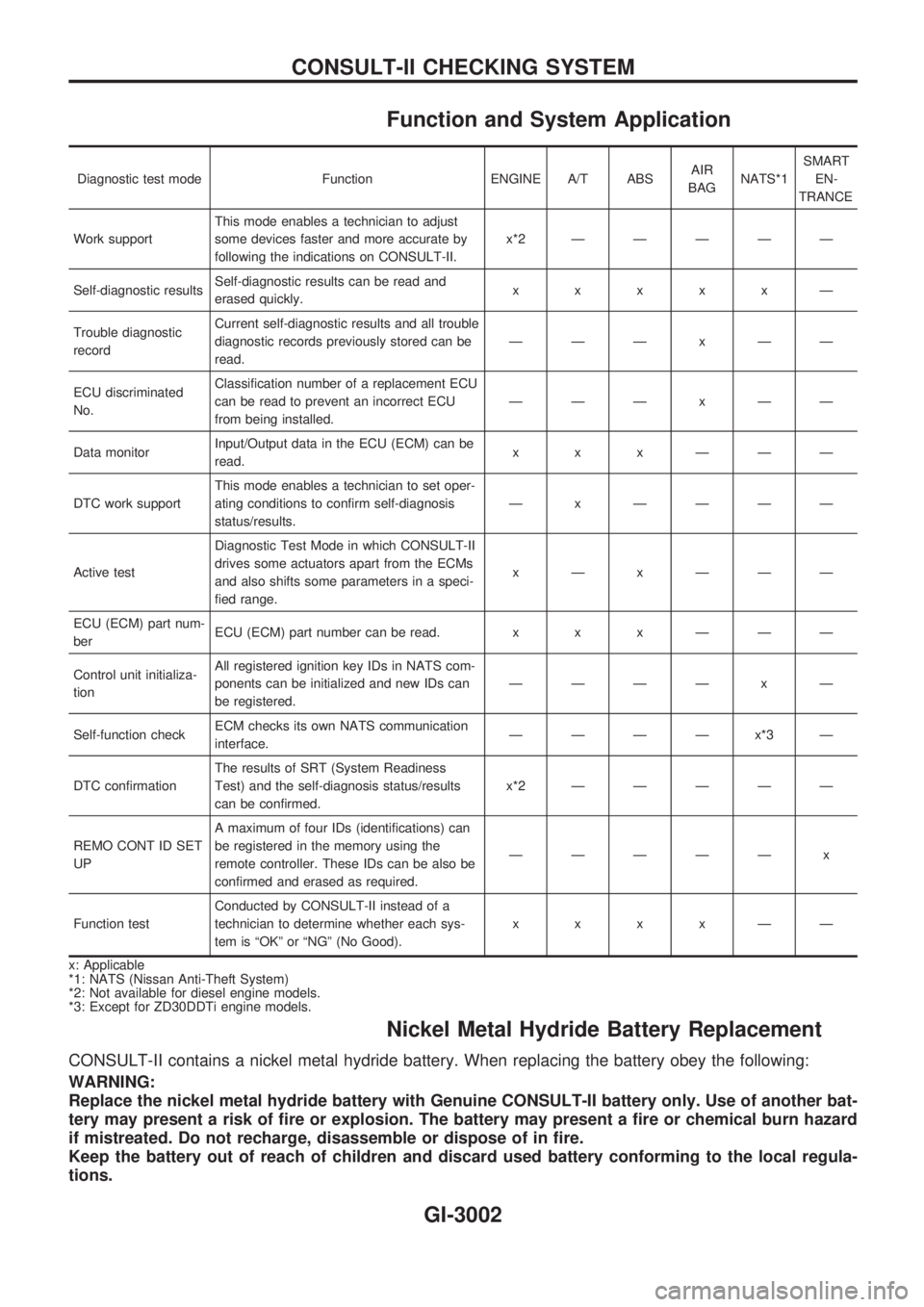
Function and System Application
Diagnostic test mode Function ENGINE A/T ABSAIR
BAGNATS*1SMART
EN-
TRANCE
Work supportThis mode enables a technician to adjust
some devices faster and more accurate by
following the indications on CONSULT-II.x*2ÐÐÐÐÐ
Self-diagnostic resultsSelf-diagnostic results can be read and
erased quickly.xxxxxÐ
Trouble diagnostic
recordCurrent self-diagnostic results and all trouble
diagnostic records previously stored can be
read.ÐÐÐxÐÐ
ECU discriminated
No.Classification number of a replacement ECU
can be read to prevent an incorrect ECU
from being installed.ÐÐÐxÐÐ
Data monitorInput/Output data in the ECU (ECM) can be
read.xxxÐÐÐ
DTC work supportThis mode enables a technician to set oper-
ating conditions to confirm self-diagnosis
status/results.Ð x ÐÐÐÐ
Active testDiagnostic Test Mode in which CONSULT-II
drives some actuators apart from the ECMs
and also shifts some parameters in a speci-
fied range.xÐxÐÐÐ
ECU (ECM) part num-
berECU (ECM) part number can be read. x x x Ð Ð Ð
Control unit initializa-
tionAll registered ignition key IDs in NATS com-
ponents can be initialized and new IDs can
be registered.ÐÐÐÐ x Ð
Self-function checkECM checks its own NATS communication
interface.ÐÐÐÐx*3Ð
DTC confirmationThe results of SRT (System Readiness
Test) and the self-diagnosis status/results
can be confirmed.x*2ÐÐÐÐÐ
REMO CONT ID SET
UPA maximum of four IDs (identifications) can
be registered in the memory using the
remote controller. These IDs can be also be
confirmed and erased as required.ÐÐÐÐÐ x
Function testConducted by CONSULT-II instead of a
technician to determine whether each sys-
tem is ªOKº or ªNGº (No Good).xxxxÐÐ
x: Applicable
*1: NATS (Nissan Anti-Theft System)
*2: Not available for diesel engine models.
*3: Except for ZD30DDTi engine models.
Nickel Metal Hydride Battery Replacement
CONSULT-II contains a nickel metal hydride battery. When replacing the battery obey the following:
WARNING:
Replace the nickel metal hydride battery with Genuine CONSULT-II battery only. Use of another bat-
tery may present a risk of fire or explosion. The battery may present a fire or chemical burn hazard
if mistreated. Do not recharge, disassemble or dispose of in fire.
Keep the battery out of reach of children and discard used battery conforming to the local regula-
tions.
CONSULT-II CHECKING SYSTEM
GI-3002
Page 277 of 311
HEATER &
AIR CONDITIONER
SECTION
HA
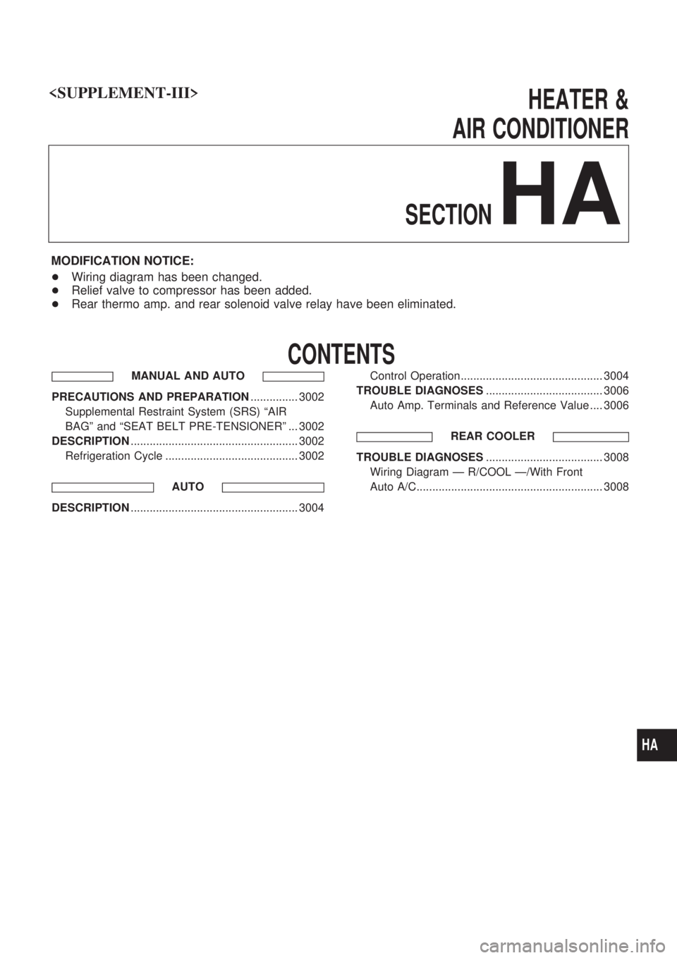
MODIFICATION NOTICE:
+Wiring diagram has been changed.
+Relief valve to compressor has been added.
+Rear thermo amp. and rear solenoid valve relay have been eliminated.
CONTENTS
MANUAL AND AUTO
PRECAUTIONS AND PREPARATION............... 3002
Supplemental Restraint System (SRS) ªAIR
BAGº and ªSEAT BELT PRE-TENSIONERº ... 3002
DESCRIPTION..................................................... 3002
Refrigeration Cycle .......................................... 3002
AUTO
DESCRIPTION..................................................... 3004Control Operation............................................. 3004
TROUBLE DIAGNOSES..................................... 3006
Auto Amp. Terminals and Reference Value .... 3006
REAR COOLER
TROUBLE DIAGNOSES..................................... 3008
Wiring Diagram Ð R/COOL Ð/With Front
Auto A/C........................................................... 3008
HA
Page 280 of 311
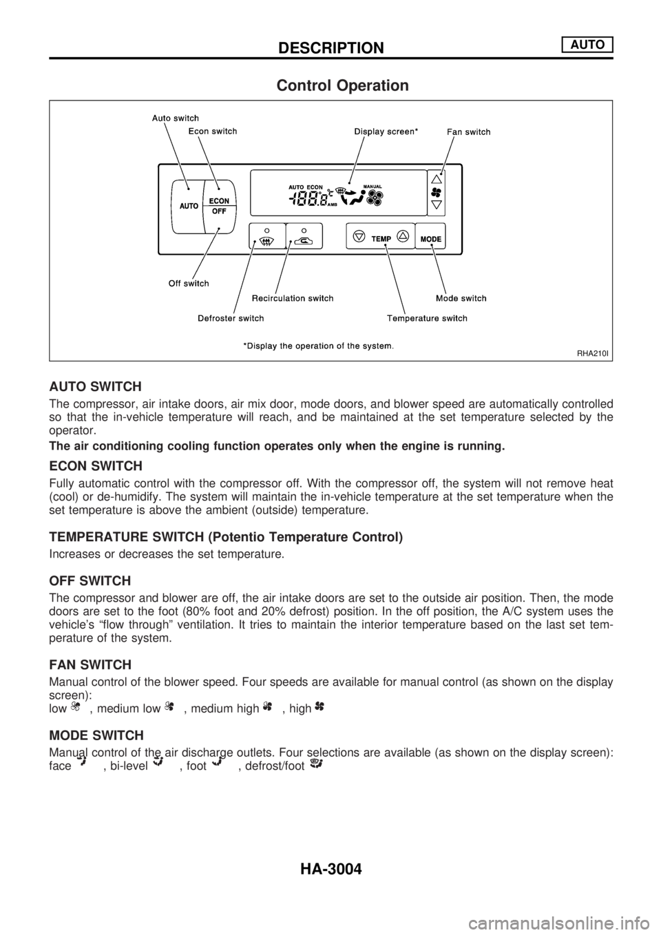
Control Operation
AUTO SWITCH
The compressor, air intake doors, air mix door, mode doors, and blower speed are automatically controlled
so that the in-vehicle temperature will reach, and be maintained at the set temperature selected by the
operator.
The air conditioning cooling function operates only when the engine is running.
ECON SWITCH
Fully automatic control with the compressor off. With the compressor off, the system will not remove heat
(cool) or de-humidify. The system will maintain the in-vehicle temperature at the set temperature when the
set temperature is above the ambient (outside) temperature.
TEMPERATURE SWITCH (Potentio Temperature Control)
Increases or decreases the set temperature.
OFF SWITCH
The compressor and blower are off, the air intake doors are set to the outside air position. Then, the mode
doors are set to the foot (80% foot and 20% defrost) position. In the off position, the A/C system uses the
vehicle's ªflow throughº ventilation. It tries to maintain the interior temperature based on the last set tem-
perature of the system.
FAN SWITCH
Manual control of the blower speed. Four speeds are available for manual control (as shown on the display
screen):
low
, medium low, medium high, high
MODE SWITCH
Manual control of the air discharge outlets. Four selections are available (as shown on the display screen):
face
, bi-level, foot, defrost/foot
RHA210I
DESCRIPTIONAUTO
HA-3004
Page 283 of 311
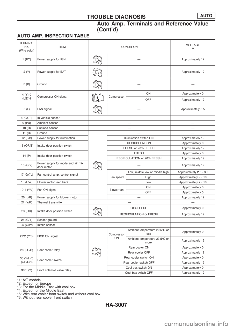
AUTO AMP. INSPECTION TABLE
TERMINAL
No.
(Wire color)ITEM CONDITIONVOLTAGE
V
1 (RY) Power supply for IGN
Ð Approximately 12
2 (Y) Power supply for BAT
Ð Approximately 12
3 (B) Ground
ÐÐ
4 (Y)*2
(LG)*4Compressor ON signal
CompressorON Approximately 0
OFF Approximately 12
5 (L) LAN signal
Ð Approximately 5.5
8 (GY/R) In-vehicle sensor Ð Ð
9 (PU) Ambient sensor Ð Ð
10 (R) Sunload sensor Ð Ð
11 (B) Ground
ÐÐ
12 (L/B) Power supply for illumination Illumination switch ON Approximately 12
13 (OR/B) Intake door position switchRECIRCULATION Approximately 0
FRESH or 20% FRESH Approximately 12
14 (P) Intake door position switchFRESH Approximately 0
RECIRCULATION or 20% FRESH Approximately 12
15 (G/Y)Power supply for mode and air mix
door motorÐ Approximately 12
17 (GY/L) Fan control amp. control signal
Fan speedLow, middle low or middle high Approximately 2.5 - 3.0
High Approximately9-10
18 (L/W) Blower motor feed back Low Approximately7-10
19*1 (Y/L) Fan ON signal Blower fanON Approximately 0
OFF Approximately 5
20 (L/R) Power supply for blower motor Ð Approximately 12
21 (Y/R) Thermal transmitter Ð Ð
23 (OR) Intake door position switch
20% FRESH Approximately 0
RECIRCULATION or FRESH Approximately 12
24 (G/Y) Sensor ground Ð Ð
25 (G/W) Intake sensor Ð Ð
27*2 (Y/B) FICD ON signal
Compressor
ONAmbient temperature 20.5ÉC or
lessApproximately 0
Ambient temperature 23.5ÉC or
moreApproximately 12
28 (LG/B) Rear cooler relayRear cooler ON Approximately 0
Rear cooler OFF Approximately 12
35 (Y/L)*5
(OR/L)*6Rear cooler switchRear cooler switch ON Approximately 0
Rear cooler switch OFF Approximately 12
36*3 (Y) Front solenoid valve relayCool box switch ON Approximately 0
Cool box switch OFF Approximately 12
*1: A/T models
*2: Except for Europe
*3: For the Middle East with cool box
*4: Except for the Middle East
*5: With rear cooler front switch and without cool box
*6: Without rear cooler front switch
TROUBLE DIAGNOSISAUTO
Auto Amp. Terminals and Reference Value
(Cont'd)
HA-3007