2002 NISSAN MAXIMA wheel
[x] Cancel search: wheelPage 66 of 247

nate when low or high is selected.
The heater is controlled by a thermostat,
automatically turning the heater on and off.
The indicator light will remain on as long as
the switch is on.
3. When the vehicle's interior is warmed, or
before you leave the vehicle, be sure to turn
the switch to the off position (center).
CAUTION
IThe battery could run down if the seat
heater is operated while the engine is
not running.
IDo not use the seat heater for ex-
tended periods or when no one is
using the seat.
IDo not put anything on the seat which
insulates heat, such as a blanket,
cushion, seat cover, etc. Otherwise,
the seat may become overheated.
IDo not place anything hard or heavy
on the seat or pierce it with a pin or
similar object. This may result in
damage to the heater.IAny liquid spilled on the heated seat
should be removed immediately with
a dry cloth.
IWhen cleaning the seat, never use
gasoline, thinner, or any similar ma-
terials.
IIf any abnormalities are found or the
heated seat does not operate, turn
the switch off and have the system
checked by your NISSAN dealer.
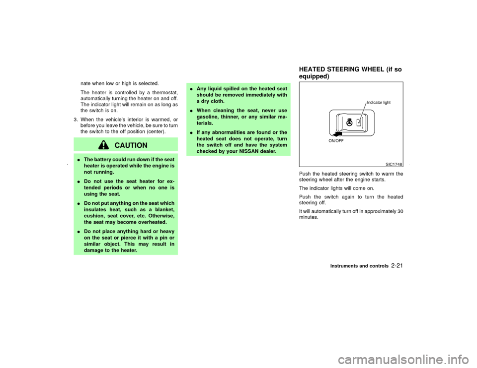
Push the heated steering switch to warm the
steering wheel after the engine starts.
The indicator lights will come on.
Push the switch again to turn the heated
steering off.
It will automatically turn off in approximately 30
minutes.
SIC1748
HEATED STEERING WHEEL (if so
equipped)
Instruments and controls
2-21
Z
01.9.21/A33-D/V5.0
X
Page 86 of 247

3 Pre-driving checks and adjustmentsKeys .......................................................................... 3-2
Doors ......................................................................... 3-2
Locking with key ................................................... 3-3
Front window open/close with key ....................... 3-3
Locking with inside lock knob............................... 3-3
Locking with power door lock switch.................... 3-4
Child safety rear door lock ................................... 3-4
Remote keyless entry system ................................... 3-4
How to use remote keyless entry system ............ 3-5
Battery replacement ............................................. 3-8
Hood ........................................................................ 3-10
Trunk lid .................................................................. 3-10
Opener operation ............................................... 3-11
Key operation ..................................................... 3-11Interior trunk lid release ..................................... 3-12
Fuel filler lid ............................................................. 3-12
Opener operation ............................................... 3-12
Fuel filler cap ...................................................... 3-13
Steering wheel ........................................................ 3-14
Tilt operation....................................................... 3-14
Sun visors ............................................................... 3-14
Mirrors ..................................................................... 3-15
Automatic anti-glare inside mirror ...................... 3-15
Outside mirrors ................................................... 3-15
Automatic seat positioner (if so equipped) ............. 3-16
Automatic seat positioner operation (A/T models
only) .................................................................... 3-16
Procedure for storing memory............................ 3-17
Z
01.9.21/A33-D/V5.0
X
Page 99 of 247

properly may cause the
mal-
function indicator lamp (MIL) to illu-
minate. If the
lamp illuminates
because the fuel filler cap is loose or
missing, tighten or install the cap and
continue to drive the vehicle. The
lamp should turn off after a few
driving trips. If the
lamp does
not turn off after a few driving trips,
have the vehicle inspected by an au-
thorized NISSAN dealer.
IFor additional information, see the
ªMalfunction indicator lamp (MIL)º in
the ª2. Instruments and controlsº
section.
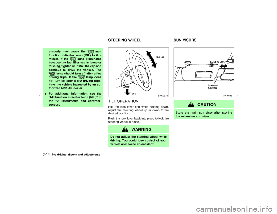
TILT OPERATIONPull the lock lever and while holding down,
adjust the steering wheel up or down to the
desired position.
Push the lock lever back into place to lock the
steering wheel in place.
WARNING
Do not adjust the steering wheel while
driving. You could lose control of your
vehicle and cause an accident.
CAUTION
Store the main sun visor after storing
the extension sun visor.
SPA0234
SPA0991
STEERING WHEEL SUN VISORS
3-14
Pre-driving checks and adjustments
Z
01.9.21/A33-D/V5.0
X
Page 102 of 247

PROCEDURE FOR STORING
MEMORYTwo positions can be stored in the automatic
driver's seat positioner memory.Follow these
procedures to use the memory system.
1. A/T models:
Set the automatic transmission selector
lever to the P (Park) position.
M/T models:
Apply the parking brake securely when the
vehicle is stopped.
2. Turn the ignition ON.
3. Adjust the driver's seat and steering column
to the desired positions by manually oper-
ating each adjusting switch. For additional
information, see ªSeatsº in the ª1. Seats,
restraints and supplemental air bag sys-
temsº section and ªSteering wheelº earlier
in this section.During this step, do not turn the ignition to
any positions other than ON.
4. Push the SET switch and, within 5 seconds,
push the memory switch 1 or 2 fully for at
least 1 second.
The indicator light for the pushed memory
switch will come on and stay on for approxi-
mately 5 seconds after pushing the switch.
After the indicator light goes off, the se-
lected positions are stored in the selected
memory (1 or 2).
If memory is stored in the same memory
switch, the previous memory will be de-
leted.
Confirming memory storageITurn the ignition ON and push the SET
switch. If the main memory has not been
stored, the indicator light will come on for
approximately 0.5 seconds. When the
memory has stored the position, the indica-
tor light will stay on for approximately 5
seconds.
IIf the battery cable is disconnected, or if the
fuse blows, the memory will be canceled. In
such a case, reset the desired positions
using the following procedures.
1. Open and close the driver's door more than
SPA1385
Pre-driving checks and adjustments
3-17
Z
01.9.21/A33-D/V5.0
X
Page 133 of 247

CD CARE AND CLEANINGIHandle a CD by its edges. Never touch the
surface of the disc. Do not bend the disc.
IAlways place the discs in the storage case
when they are not being used.
ITo clean a disc, wipe the surface from the
center to the outer edge using a clean, soft
cloth. Do not wipe the disc using a circular
motion.
Do not use a conventional record cleaner or
alcohol intended for industrial use.
IA new disc may be rough on its inner and
outer edges. Remove the rough edges us-
ing the side of a pen or pencil as illustrated.
STEERING SWITCH FOR AUDIO
CONTROLThe audio system can be operated using the
controls on the steering wheel.MODE select switchPush the mode select switch to change the
mode in the sequence of AM, FM1, FM2, CD
and CD autochanger (if so equipped) and
Tape.Volume control switchesPush the upper or lower side switch to in-
crease or decrease the volume.
Tuning
Memory change (radio):
Push the tuning switch
or
for less
than 1.5 seconds to change the radio fre-
quency.
Seek tuning (radio):
Push the tuning switch
or
for more
than 1.5 seconds to seek the next or previous
radio station.
APS (Automatic Program Search) FF, APS
REW (tape/CD or CD changer):
Push the tuning switch
or
for less
1.5 seconds to return to the beginning of the
present program or skip to the next program.
Push several times to skip back or skip
through programs.
This system searches for the blank intervals
between selections. If there is a blank interval
within one program or there is no interval
between programs, the system may not stop in
the desired or expected location.
FF REW (tape or CD changer):
Push the tuning switch
or
for more
than 1.5 seconds to rewind or fast forward the
tape or to change the playing disc up or down.
To stop the FF or REW function, press the
SAA0451
SAA0545
4-28
Heater, air conditioner and audio systems
Z
01.9.21/A33-D/V5.0
X
Page 140 of 247

LOCK position, proceed as follows to remove
the key:
1. Move the selector lever into the P (Park)
position.
2. Turn the ignition key slightly in the ON
direction.
3. Turn the key toward the LOCK position.
4. Remove the key.
If the key is removed from the ignition switch,
the selector lever cannot be moved from P
(Park) position.The selector lever can be
moved if the ignition switch is in the ON
position and the foot brake pedal is de-
pressed.
There is an OFF position in between LOCK
and ACC, although it does not show on the
lock cylinder. When the ignition is in OFF the
steering wheel is not locked.
In order for the steering wheel to be locked, it
must be turned about 1/6 of a turn counter-
clockwise from the straight up position.
To lock the steering wheel, turn the key to
the LOCK position. Remove the key. To
unlock the steering wheel, insert the key
and turn it gently while rotating the steer-
ing wheel slightly right and left.
WARNING
Never remove or turn the key to the
LOCK position while driving. The steer-
ing wheel will lock. This may cause the
driver to lose control of the vehicle and
could result in serious vehicle damage
and/or personal injury.
MANUAL TRANSMISSIONThe switch includes an anti-theft steering lock
device.
LOCK Normal parking position (0)
The ignition key can only be removed when
the switch is in this position.
On manual transmission models, to turn the
ignition key to LOCK from ACC or ON, first turn
the key to OFF and turn the key to LOCK while
pushing the key in.
In order for the steering wheel to be locked, it
must be turned about 1/6 of a turn clockwise
from the straight up position.
SSD0082C
Starting and driving
5-5
Z
01.9.21/A33-D/V5.0
X
Page 141 of 247

To lock the steering wheel, turn the key to
the LOCK position. Remove the key. To
unlock the steering wheel, insert the key
and turn it gently while rotating the steer-
ing wheel slightly right and left.
WARNING
Never remove or turn the key to the
LOCK position while driving. The steer-
ing wheel will lock. This may cause the
driver to lose control of the vehicle and
could result in serious vehicle damage
and/or personal injury.
KEY POSITIONSThe switch includes an anti-theft steering lock
device.
LOCK (Normal parking position) (0)
The ignition key can only be removed when
the switch is in this position.
OFF (1)
The engine can be turned off without locking
the steering wheel.
ACC (Accessories) (2)
This position activates electrical accessories
such as the radio when the engine is not
running.
ON (Normal operating position) (3)
This position turns on the ignition system and
the electrical accessories.
START (4)
This position activates the starter motor, start-
ing the engine.NISSAN VEHICLE IMMOBILIZER
SYSTEMThe Nissan Vehicle Immobilizer System will
not allow the engine to start without the use ofthe registered Nissan Vehicle Immobilizer Sys-
tem key.
If the engine fails to start using the registered
Nissan Vehicle Immobilizer System key, it may
be due to interference caused by another
Nissan Vehicle Immobilizer System key, an
automated toll road device or automated pay-
ment device on the key ring. Restart the en-
gine using the following procedures:
1. Leave the ignition switch in the ON position
for approximately 5 seconds.
2. Turn the ignition switch to the OFF or LOCK
position and wait approximately 10 sec-
onds.
3. Repeat step 1 and 2 again.
4. Restart the engine while holding the device
(which may have caused the interference)
separate from the registered Nissan Ve-
hicle Immobilizer System key.
If this procedure allows the engine to start,
NISSAN recommends placing the registered
Nissan Vehicle Immobilizer System key on a
separate key ring to avoid interference from
other devices.
5-6
Starting and driving
Z
01.9.21/A33-D/V5.0
X
Page 145 of 247

3 (Third gear):
For driving up or down long slopes where
engine braking would be advantageous.
2 (Second gear):
Use for hill climbing or engine braking on
downhill grades.
Do not exceed 68 MPH (110 km/h) in the 2
(Second gear) position.
1 (Low gear):
Use this position when climbing steep hills
slowly or driving slowly through deep snow,
sand or mud, or for maximum engine braking
on steep downhill grades.
Do not exceed 37 MPH (60 km/h) in the 1 (Low
gear) position.
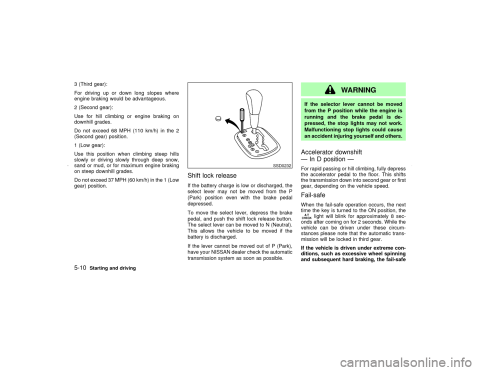
Shift lock releaseIf the battery charge is low or discharged, the
select lever may not be moved from the P
(Park) position even with the brake pedal
depressed.
To move the select lever, depress the brake
pedal, and push the shift lock release button.
The select lever can be moved to N (Neutral).
This allows the vehicle to be moved if the
battery is discharged.
If the lever cannot be moved out of P (Park),
have your NISSAN dealer check the automatic
transmission system as soon as possible.
WARNING
If the selector lever cannot be moved
from the P position while the engine is
running and the brake pedal is de-
pressed, the stop lights may not work.
Malfunctioning stop lights could cause
an accident injuring yourself and others.Accelerator downshift
Ð In D position ÐFor rapid passing or hill climbing, fully depress
the accelerator pedal to the floor. This shifts
the transmission down into second gear or first
gear, depending on the vehicle speed.Fail-safeWhen the fail-safe operation occurs, the next
time the key is turned to the ON position, the
light will blink for approximately 8 sec-
onds after coming on for 2 seconds. While the
vehicle can be driven under these circum-
stances please note that the automatic trans-
mission will be locked in third gear.
If the vehicle is driven under extreme con-
ditions, such as excessive wheel spinning
and subsequent hard braking, the fail-safe
SSD0232
5-10
Starting and driving
Z
01.9.21/A33-D/V5.0
X