2002 NISSAN MAXIMA fuel
[x] Cancel search: fuelPage 56 of 247
fuel economy, and possible damage to
the emission control system.
Slip indicator light (if so
equipped)
This light will blink on when your traction
control system (TCS) is limiting wheel spin.
Slippery road conditions may exist if the slip
indicator light blinks on. If this happens, adjust
your driving accordingly.
You may feel or hear the system working, but
this is normal.
The light will blink on for a few seconds after
the traction control system stops limiting wheel
spin.
The slip indicator light also comes on when
you turn the ignition key to ON. The light will
turn off after about 2 seconds if the system is
operational. If the light does not come on or go
off, have the traction control system checked
by your NISSAN dealer. The system operates
in all transmission shift lever positions. But the
system can upshift the transmission only as
high as the indicated shift lever position.
Traction control system
indicator light (if so equipped)
After turning the ignition key to the ON posi-
tion, the light will illuminate. The light will turn
off after about 2 seconds if the traction control
system (TCS) is operational.
If the light stays on or comes on when you are
driving, it may indicate the traction control
system is not functioning properly. Have the
system checked by your NISSAN dealer.
The traction control system indicator light may
come on for the following reasons.
a) If the system is turned off by pressing
the button on the instrument panel, the
indicator light will come on and stay on.
To turn the system back on, press the
button again. The indicator light will go
off.
b) If engine speed is above 4,000 rpm in a
selected gear. Use D range on low fric-
tion road surfaces.
If the traction control system indicator light
comes on and stays on for an extended period
of time when the system is turned on, have
your vehicle checked by your NISSAN dealer.
Turn signal/hazard indicator
lights
The light flashes when the turn signal switch
lever or hazard switch is turned on.AUDIBLE REMINDERS
Key reminder chimeThe chime will sound if the driver's side door is
opened while the key is left in the ignition
switch (ignition switch is turned off). Remove
the key and take it with you when leaving the
vehicle.Light reminder chimeThe chime will sound when the front door is
opened with the headlight switch on unless the
ignition key is in the ON position.
Make sure to turn the light switch off when you
leave the vehicle.Seat belt warning chimeThe chime will sound for about 6 seconds
unless the drivers seat belt is securely fas-
tened.Brake pad wear warningThe disc brake pads have audible wear warn-
ings. When a brake pad requires replacement,
Instruments and controls
2-11
Z
01.9.21/A33-D/V5.0
X
Page 76 of 247
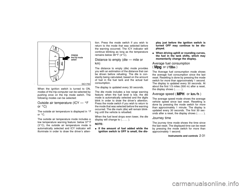
When the ignition switch is turned to ON,
modes of the trip computer can be selected by
pushing once on the trip mode switch. The
following modes can be selected:Outside air temperature (ICY Ð ÉF
or ÉC)The outside air temperature is displayed in ÉF
or ÉC.
The outside air temperature mode includes a
low temperature warning feature: below 37ÉF
(3ÉC), the outside air temperature mode is
automatically selected and ICY indicator will
illuminate in order to draw the driver's atten-tion. Press the mode switch if you wish to
return to the mode that was selected before
the warning occurred. The ICY indicator will
continue blinking as long as the temperature
remains below 39ÉF (4ÉC).
Distance to empty (dte Ð mile or
km)The distance to empty (dte) mode provides
you with an estimation of the distance that can
be driven before refueling. The dte is con-
stantly being calculated, based on the amount
of fuel in the fuel tank and the actual fuel
consumption.
The display is updated every 30 seconds.
The dte mode includes a low range warning
feature: when the fuel level is low, the dte
mode is automatically selected and the digits
blink in order to draw the driver's attention.
Press the mode switch if you wish to return to
the mode that was selected before the warning
occurred. The dte mark (dte) will remain blink-
ing until the vehicle is refuelled.
When the fuel level drops even lower, the dte
display will change to (
).
NOTE:
IIf the amount of fuel added while the
ignition switch is OFF is small, the dis-play just before the ignition switch is
turned OFF may continue to be dis-
played.
IWhen driving uphill or rounding curves,
the fuel in the tank shifts, which may
momentarily change the display.
Average fuel consumption
(
or
)
The Average fuel consumption mode shows
the average fuel consumption since the last
reset. Resetting is done by pressing the mode
switch for more than approximately 1 second.
The display is updated every 30 seconds. At
about the first 1/3 miles (500 m) after a reset,
the display shows (
).
Average speed (
or
)
The average speed mode shows the average
vehicle speed since last reset. Resetting is
done by pressing the mode switch for more
than approximately 1 minute. The display is
updated every 30 seconds. The first 30 sec-
onds after a reset, the display shows (
).
Journey timeThe journey time mode shows the time since
the last reset. The displayed time can be reset
by pressing the mode switch for more than
approximately 1 second.
SIC1750
Instruments and controls
2-31
Z
01.9.21/A33-D/V5.0
X
Page 86 of 247

3 Pre-driving checks and adjustmentsKeys .......................................................................... 3-2
Doors ......................................................................... 3-2
Locking with key ................................................... 3-3
Front window open/close with key ....................... 3-3
Locking with inside lock knob............................... 3-3
Locking with power door lock switch.................... 3-4
Child safety rear door lock ................................... 3-4
Remote keyless entry system ................................... 3-4
How to use remote keyless entry system ............ 3-5
Battery replacement ............................................. 3-8
Hood ........................................................................ 3-10
Trunk lid .................................................................. 3-10
Opener operation ............................................... 3-11
Key operation ..................................................... 3-11Interior trunk lid release ..................................... 3-12
Fuel filler lid ............................................................. 3-12
Opener operation ............................................... 3-12
Fuel filler cap ...................................................... 3-13
Steering wheel ........................................................ 3-14
Tilt operation....................................................... 3-14
Sun visors ............................................................... 3-14
Mirrors ..................................................................... 3-15
Automatic anti-glare inside mirror ...................... 3-15
Outside mirrors ................................................... 3-15
Automatic seat positioner (if so equipped) ............. 3-16
Automatic seat positioner operation (A/T models
only) .................................................................... 3-16
Procedure for storing memory............................ 3-17
Z
01.9.21/A33-D/V5.0
X
Page 97 of 247
INTERIOR TRUNK LID RELEASE
WARNING
Closely supervise children when they
are around cars to prevent them from
playing and becoming locked in the
trunk where they could be seriously in-
jured. Keep the car locked, with the
trunk closed, when not in use, and pre-
vent children's access to car keys.
The interior trunk lid release mechanism pro-vides a means of escape for children and
adults in the event they become locked inside
the trunk.
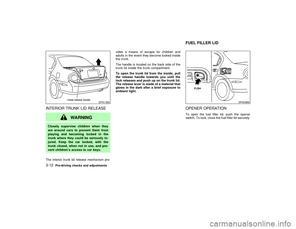
The handle is located on the back side of the
trunk lid inside the trunk compartment.
To open the trunk lid from the inside, pull
the release handle towards you until the
lock releases and push up on the trunk lid.
The release lever is made of a material that
glows in the dark after a brief exposure to
ambient light.
OPENER OPERATIONTo open the fuel filler lid, push the opener
switch. To lock, close the fuel filler lid securely.
SPA1382
SPA0986
FUEL FILLER LID
3-12
Pre-driving checks and adjustments
Z
01.9.21/A33-D/V5.0
X
Page 98 of 247
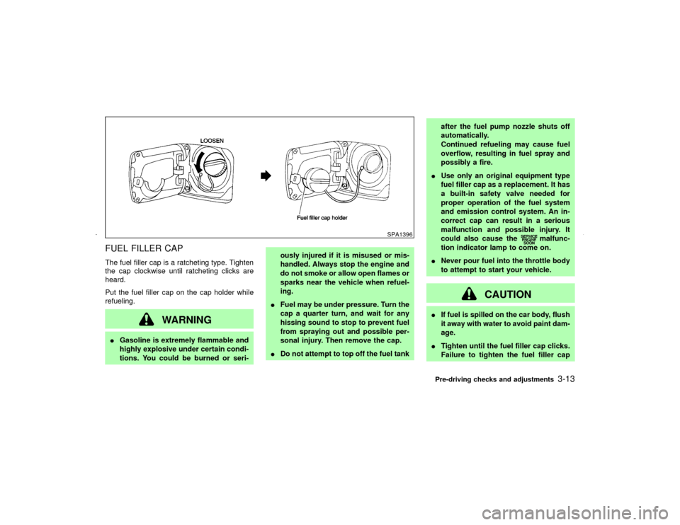
FUEL FILLER CAPThe fuel filler cap is a ratcheting type. Tighten
the cap clockwise until ratcheting clicks are
heard.
Put the fuel filler cap on the cap holder while
refueling.
WARNING
IGasoline is extremely flammable and
highly explosive under certain condi-
tions. You could be burned or seri-ously injured if it is misused or mis-
handled. Always stop the engine and
do not smoke or allow open flames or
sparks near the vehicle when refuel-
ing.
IFuel may be under pressure. Turn the
cap a quarter turn, and wait for any
hissing sound to stop to prevent fuel
from spraying out and possible per-
sonal injury. Then remove the cap.
IDo not attempt to top off the fuel tankafter the fuel pump nozzle shuts off
automatically.
Continued refueling may cause fuel
overflow, resulting in fuel spray and
possibly a fire.
IUse only an original equipment type
fuel filler cap as a replacement. It has
a built-in safety valve needed for
proper operation of the fuel system
and emission control system. An in-
correct cap can result in a serious
malfunction and possible injury. It
could also cause the
malfunc-
tion indicator lamp to come on.
INever pour fuel into the throttle body
to attempt to start your vehicle.
CAUTION
IIf fuel is spilled on the car body, flush
it away with water to avoid paint dam-
age.
ITighten until the fuel filler cap clicks.
Failure to tighten the fuel filler cap
SPA1396
Pre-driving checks and adjustments
3-13
Z
01.9.21/A33-D/V5.0
X
Page 99 of 247
properly may cause the
mal-
function indicator lamp (MIL) to illu-
minate. If the
lamp illuminates
because the fuel filler cap is loose or
missing, tighten or install the cap and
continue to drive the vehicle. The
lamp should turn off after a few
driving trips. If the
lamp does
not turn off after a few driving trips,
have the vehicle inspected by an au-
thorized NISSAN dealer.
IFor additional information, see the
ªMalfunction indicator lamp (MIL)º in
the ª2. Instruments and controlsº
section.
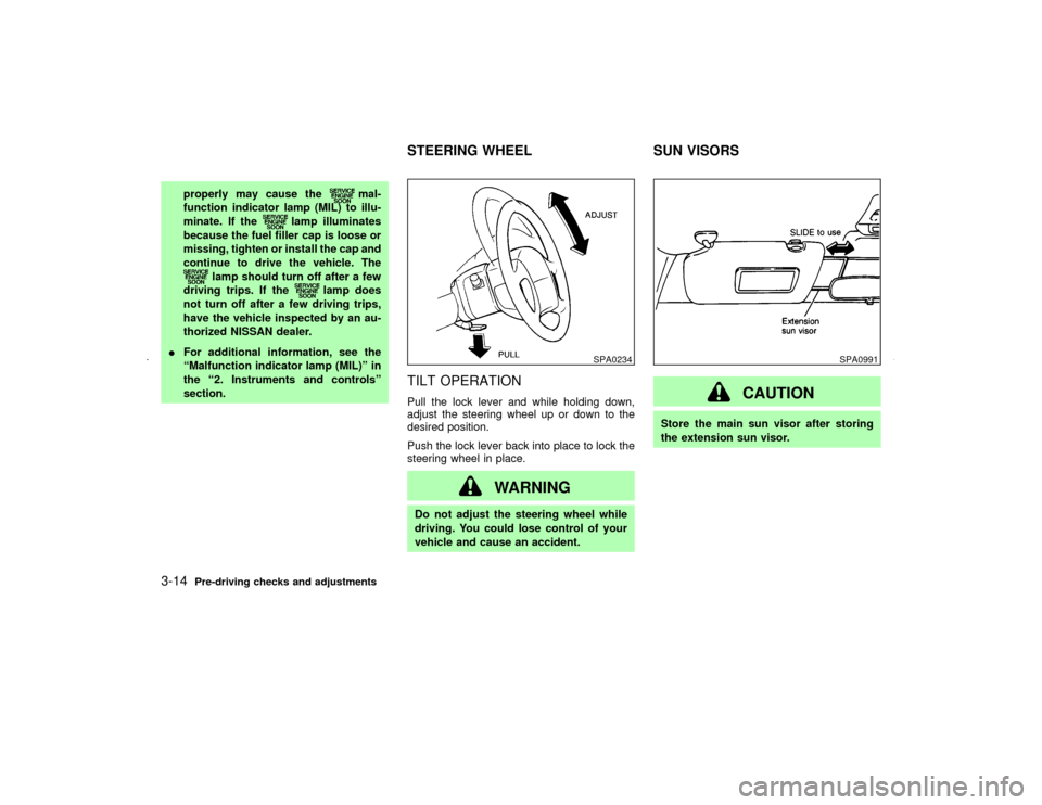
TILT OPERATIONPull the lock lever and while holding down,
adjust the steering wheel up or down to the
desired position.
Push the lock lever back into place to lock the
steering wheel in place.
WARNING
Do not adjust the steering wheel while
driving. You could lose control of your
vehicle and cause an accident.
CAUTION
Store the main sun visor after storing
the extension sun visor.
SPA0234
SPA0991
STEERING WHEEL SUN VISORS
3-14
Pre-driving checks and adjustments
Z
01.9.21/A33-D/V5.0
X
Page 117 of 247
The air conditioning system in your NISSAN
vehicle is charged with a refrigerant designed
with the environment in mind.This refrigerant
will not harm the earth's ozone layer.How-
ever, special charging equipment and lubricant
are required when servicing your NISSAN air
conditioner. Using improper refrigerants or lu-
bricants will cause severe damage to your air
conditioning system. See ªCapacities and rec-
ommended fuel/lubricantsº in the ª9. Technical
and consumer informationº section for air con-
ditioning system refrigerant and lubricant rec-
ommendations.
Your NISSAN dealer will be able to service
your environmentally friendly air conditioning
system.
WARNING
The air conditioner system contains re-
frigerant under high pressure. To avoid
personal injury, any air conditioner ser-
vice should be done only by an experi-
enced technician with proper equip-
ment.Turn the ignition key to ACC or ON and press
the power on switch to turn on the radio. If you
listen to the radio with the engine not running,
the key should be turned to the ACC position.
Radio reception is affected by station signal
strength, distance from radio transmitter, build-
ings, bridges, mountains and other external
influences. Intermittent changes in reception
quality normally are caused by these external
influences.
Using a cellular phone in or near the ve-
hicle may influence radio reception quality.
Radio receptionYour radio system is equipped with state-of-
the-art electronic circuits to enhance radio
reception. These circuits are designed to ex-
tend reception range, and to enhance the
quality of that reception.
However there are some general characteris-
tics of both FM and AM radio signals that can
affect radio reception quality in a moving ve-
hicle, even when the finest equipment is used.
These characteristics are completely normal in
a given reception area, and do not indicate any
malfunction in your radio system.
Remember that a moving vehicle is not the
ideal place to listen to a radio. Because of the
movement, reception conditions will constantlychange. Buildings, terrain, signal distance and
interference from other vehicles can work
against ideal reception. Described below are
some of the factors that can affect your radio
reception.
SERVICING AIR CONDITIONER AUDIO SYSTEM4-12
Heater, air conditioner and audio systems
Z
01.9.21/A33-D/V5.0
X
Page 135 of 247
Disc removalIPull the * marked area with your fingers.
IUse your fingertips to grasp the center part
of the disc and remove the disc.
CAUTION
IDo not touch the playing surface of
the disc.
IDo not use 8 cm discs. They may
cause player damage even if using
with the optional adapter.When installing a CB, ham radio or car phone
in your NISSAN, be sure to observe the follow-
ing cautions, otherwise the new equipment
may adversely affect the Engine control sys-
tem and other electronic parts.
WARNING
IA cellular telephone should not be
used while driving so full attention
may be given to vehicle operation.
Some jurisdictions prohibit the use of
cellular telephones while driving.
IIf you must make a call while your
vehicle is in motion, the hands free
cellular phone operational mode (if
so equipped) is highly recommended.
Exercise extreme caution at all times
so full attention may be given to ve-
hicle operation.
IIf a conversation in a moving vehicle
requires you to take notes, pull off the
road to a safe location and stop your
vehicle before doing so.
CAUTION
IKeep the antenna as far as possible
away from the Engine Control Module
(ECM).
IKeep the antenna wire more than 8 in
(20 cm) away from the Multiport Fuel
Injection harness. Do not route the
antenna wire next to any harness.
IAdjust the antenna standing-wave ra-
tio as recommended by the manufac-
turer.
IConnect the ground wire from the CB
radio chassis to the body.
IFor details, consult an authorized
NISSAN dealer.
CAR PHONE OR CB RADIO
4-30
Heater, air conditioner and audio systems
Z
01.9.21/A33-D/V5.0
X