2002 MINI Hardtop 2 Door wheel
[x] Cancel search: wheelPage 37 of 140

35
OVERVIEW REPAIRS OPERATIONCONTROLS DATA INDEX
SAFETY BELTS STEERING WHEEL Drive with your safety belt onEven though there is an airbag, wear a
safety belt every time you get in the
vehicle, because airbags enhance safety by
providing added protection.To fastenMake sure you hear the lock engage in the
belt buckle.To release1. Press the red button in the belt buckle
2. Hold the belt
3. Guide the belt back into its reel.
Safety belt height adjustmentUse the height adjustment mechanism to
adapt the safety belt to the ideal position
for your own body:
Press the button and at the same time push
the entire unit upwards or downwards.
Also observe the instructions on adjusting
the seats on page 31.
If the safety belts are damaged or
stretched in an accident: have the
safety belt system replaced by your MINI
center and the belt anchors checked, other-
wise the safety function can no longer be
guaranteed. If a child-restraint system was
in the vehicle during an accident, consult
the manufacturer's instructions regarding
replacement.<
To adjust the steering wheel height1. Push the locking lever downward
2. Adjust the desired steering wheel
position
3. Pull the lever back in.
Do not adjust the steering wheel
while the vehicle is moving, other-
wise unexpected movement could increase
the risk of accident.<
Page 40 of 140

38
AIRBAGS TRANSPORTING CHILDRENDo not make any changes yourself to the
individual components and wiring. This
includes the padded cover of the steering
wheel, in the instrument panel and the roof
supports, as well as the sides of the roof-
liner and the original backrest covers on the
front seats. Do not attempt to remove or
dismantle the steering wheel. In view of
the applicable safety regulations, arrange
for your MINI center to dispose of the
airbag generators. Unprofessional
attempts to service the system could lead
to failure in an emergency or undesired
airbag activation, either of which could
result in personal injury. Do not touch the
individual components directly after the
system has been triggered, as otherwise
there is a danger of burns.<
At all times, occupants should sit
upright and be properly restrained
(infants and small children in appropriate
child-restraint systems; larger children and
adults using the safety belts). Never let an
occupant's head rest near or on a head
airbag because the inflating airbag could
cause serious or fatal injury. A child which
is not properly restrained could place his or
her head on or near the airbag.<
Indicator lamp
The indicator lamp on the instru-
ment panel shows the airbag
system status starting from igni-
tion key position 1.
System operational:
>The indicator lamp comes on briefly.
System malfunction:
>The indicator lamp does not come on
>The indicator lamp fails to go out after
the engine has been started, or it comes
on during normal driving.
A system defect could prevent the airbags
from deploying in response to a severe
impact occurring within the system's
normal triggering range.
Have the system checked as soon as
possible by your MINI center.
Children younger than 13 years and/or
smaller than 5 ft (150 cm) should only
travel in the rear in suitable restraint
systems.
Commercially-available child-restraint
systems are designed to be secured with a
lap belt or with the lap belt portion of a
combination lap/shoulder belt. Improperly
or inadequately installed restraint systems
can increase the risk of injury to children.
Always read and follow the instructions
that come with the system.
If you use a child-restraint system with a
tether strap:
Page 44 of 140

42
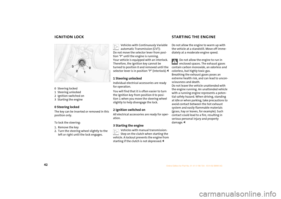
IGNITION LOCK STARTING THE ENGINE 0 Steering locked
1 Steering unlocked
2 Ignition switched on
3 Starting the engine0 Steering locked The key can be inserted or removed in this
position only.
To lock the steering:
1. Remove the key
2. Turn the steering wheel slightly to the
left or right until the lock engages.
Vehicles with Continuously Variable
automatic Transmission (CVT):
Do not move the selector lever from posi-
tion "P" until the engine is running.
Your vehicle is equipped with an interlock.
Therefore, the ignition key cannot be
turned to position 0 and removed until the
selector lever is in position "P" (Interlock).<
1 Steering unlocked Individual electrical accessories are ready
for operation.
You will find that it is often easier to turn
the ignition key from position 0 to posi-
tion 1 when you move the steering wheel
slightly to help disengage the lock.2 Ignition switched onAll electrical accessories are ready for oper-
ation.3 Starting the engine
Vehicles with manual transmission:
Step on the clutch when starting the
vehicle. A lockout prevents the engine from
starting if the clutch is not depressed.<
Do not allow the engine to warm up with
the vehicle at a standstill. Move off imme-
diately at a moderate engine speed.
Do not allow the engine to run in
enclosed spaces. The exhaust gases
contain carbon monoxide, an odorless and
colorless, but highly toxic gas.
Breathing the exhaust gases poses an
extreme health risk, and can lead to uncon-
sciousness and death.
Do not leave the vehicle unattended with
the engine running. An unattended vehicle
with a running engine represents a poten-
tial safety hazard. When driving, standing
at idle or when parking, take precautions to
avoid contact between the hot exhaust
system and easily flammable materials
(grass, hay or leaves, for example). Such
contact could lead to a fire, resulting in
serious personal injury and property
damage.<
Page 46 of 140

44
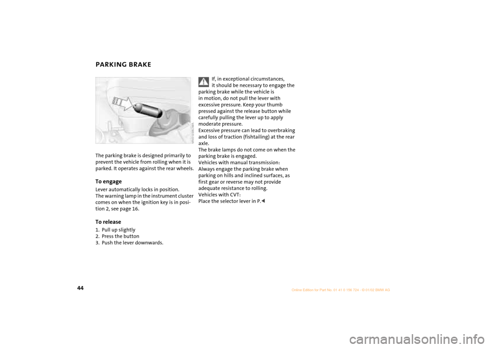
PARKING BRAKE The parking brake is designed primarily to
prevent the vehicle from rolling when it is
parked. It operates against the rear wheels.To engageLever automatically locks in position.
The warning lamp in the instrument cluster
comes on when the ignition key is in posi-
tion 2, see page 16.To release1. Pull up slightly
2. Press the button
3. Push the lever downwards.
If, in exceptional circumstances,
it should be necessary to engage the
parking brake while the vehicle is
in motion, do not pull the lever with
excessive pressure. Keep your thumb
pressed against the release button while
carefully pulling the lever up to apply
moderate pressure.
Excessive pressure can lead to overbraking
and loss of traction (fishtailing) at the rear
axle.
The brake lamps do not come on when the
parking brake is engaged.
Vehicles with manual transmission:
Always engage the parking brake when
parking on hills and inclined surfaces, as
first gear or reverse may not provide
adequate resistance to rolling.
Vehicles with CVT:
Place the selector lever in P.<
Page 49 of 140

47
OVERVIEW REPAIRS OPERATIONCONTROLS DATA INDEX
CONTINUOUSLY VARIABLE AUTOMATIC TRANSMISSION (CVT)
*
P Park
Select "P" only when the vehicle is
completely stopped. Transmission locks to
prevent rear wheels from turning.R ReverseSelect "R" only when the vehicle is
completely stopped.N NeutralSelect "N" only if your journey is inter-
rupted for a long period.D Drive (CVT driving position)This position is designed for driving under
all normal operating conditions. "Kickdown"In "kickdown", you achieve maximum
acceleration and maximum speed in posi-
tion D.
Press the accelerator pedal past the
increased resistance point at the full-
throttle position.
M/S +
Ð Manual mode and Sport
program
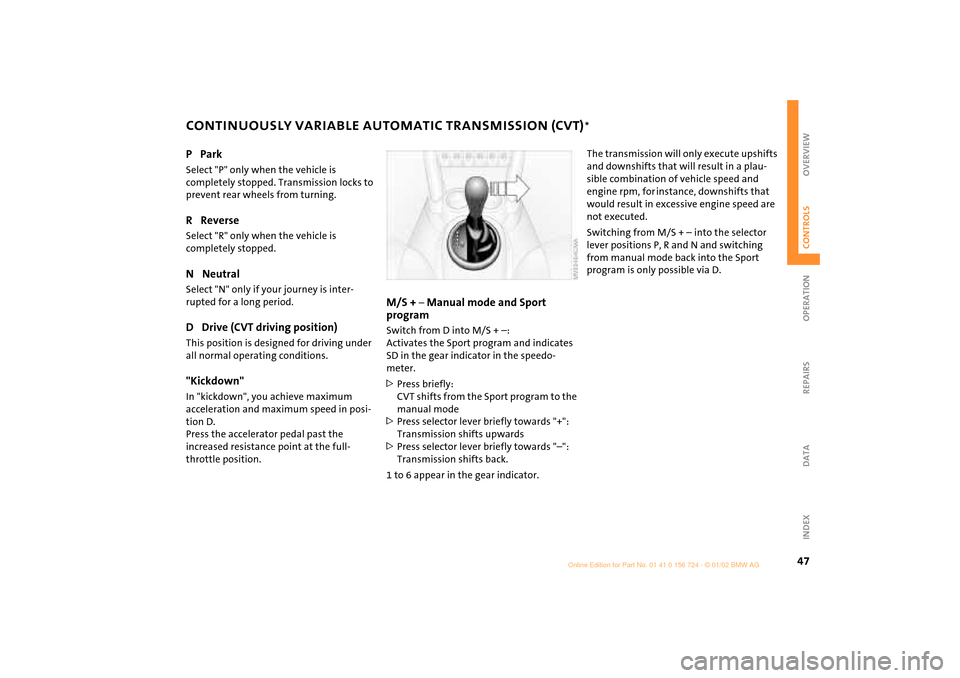
Switch from D into M/S + Ð:
Activates the Sport program and indicates
SD in the gear indicator in the speedo-
meter.
>Press briefly:
CVT shifts from the Sport program to the
manual mode
>Press selector lever briefly towards "+":
Transmission shifts upwards
>Press selector lever briefly towards "Ð":
Transmission shifts back.
1 to 6 appear in the gear indicator.
The transmission will only execute upshifts
and downshifts that will result in a plau-
sible combination of vehicle speed and
engine rpm, for instance, downshifts that
would result in excessive engine speed are
not executed.
Switching from M/S + Ð into the selector
lever positions P, R and N and switching
from manual mode back into the Sport
program is only possible via D.
Page 62 of 140

60
AUTOMATIC STABILITY CONTROL PLUS TRACTION (ASC+T)
*
The concept
This system optimizes vehicle stability and
traction, especially when just starting off,
when accelerating or when cornering.
ASC+T recognizes the danger present in
traction loss and will increase driving
stability and traction by reducing the
engine's output, and if necessary, by
applying the brakes to the front wheels.
ASC+T is operational each time you start
the engine.
The laws of physics cannot be
repealed, even with ASC+T. An appro-
priate driving style always remains the
responsibility of the driver. Avoid using the
additional safety margin provided by the
system as an excuse for taking unnecessary
risks.
Do not make any modifications to the
ASC+T system. Allow only authorized tech-
nicians to perform service procedures on
the ASC+T.<
Switch off the ASC+TBriefly press the switch.
The indicator lamp stays lit.
When driving with snow chains or to "rock
free" in snow, it can be helpful to switch off
the ASC+T for a brief period.
To maintain vehicle stability, always
drive with the ASC+T switched on
whenever possible.
Indicator lamp
The indicator lamp on the instru-
ment cluster will go out shortly
after the ignition has been
switched on, see pages 16, 17.
If the indicator lamp flashes:
ASC+T controls the drive and braking
forces.
If the indicator lamp fails to go out
after the engine is started, or if it
comes on during normal driving and stays
on:
If the system is either defective or was
switched off with the button, then the
stabilizing applications described are no
longer available. You can, however, drive
the vehicle normally without ASC+T.
In the event of a malfunction, please see
your MINI center, see pages 16, 17.<
Page 63 of 140

61
OVERVIEW REPAIRS OPERATIONCONTROLS DATA INDEX
DYNAMIC STABILITY CONTROL (DSC)
*
The concept
This system maintains driving stability
even in critical driving situations.
The system optimizes vehicle stability
during acceleration and when starting
from a full stop, as well as optimizing trac-
tion. In addition, it recognizes unstable
vehicle conditions, such as under- or over-
steering, and, as far as is possible within
the laws of physics, helps keeping the
vehicle on a steady course by reducing the
rpms and brake applications to the indi-
vidual wheels.
The DSC is operational every time you start
the engine. DSC contains the functions
Antilock Brake System ABS/Electronic Brake
Force Distribution EBV/ASC+T.
The laws of physics cannot be
repealed, even with DSC. An appro-
priate driving style always remains the
responsibility of the driver. We therefore
urge you to avoid using the additional
safety margin of the system as an excuse
for taking risks.
Do not make any modifications to the DSC
system. Allow only authorized technicians
to perform service procedures on the
DSC.<
To switch off the DSCBriefly press the switch.
The indicator lamp stays lit.
When driving with snow chains, it may be
effective to switch off the DSC for a brief
period.
To maintain stability, always drive
with the DSC switched on whenever
possible.
Indicator lamp
The indicator lamp on the instru-
ment cluster will go out shortly
after the ignition has been
switched on, see pages 16, 17.
If the indicator lamp flashes:
DSC controls the drive and braking forces.
If the indicator lamp fails to go out
after the engine is started, or if it
comes on during normal driving and stays
on:
If the system is either defective or was
switched off with the button, then the
stabilizing applications described are no
longer available. The vehicle will remain
completely operational, however, without
DSC.
In the event of a malfunction, please see
your MINI center, see pages 16, 17.<
Page 65 of 140

63
OVERVIEW REPAIRS OPERATIONCONTROLS DATA INDEX
FLAT TIRE MONITOR PARK DISTANCE CONTROL (PDC)*
Do not initialize the system when
snow chains are fitted. When driving
with snow chains, false alarms can occur or
pressure losses might not be detected.<
In the following situations false
alarms can also occur under certain
circumstances or the detection of inflation
pressure loss can be delayed:
>When driving on roads covered with
snow or on other slippery road surfaces
>A sporty driving style (slip at the driven
wheels, high lateral accelerations).<
The conceptThe PDC assists you when you back into a
parking space. A signal warns you of the
distance to an obstacle. To do this, four
ultrasonic sensors in the rear bumper
measure the distance to the nearest object.
The range for the sensors located at both
rear corners ends approx. 2 ft (60 cm)
behind the bumpers. The range for the two
middle sensors is slightly less than 5 ft
(1.5 meters).
The system starts to operate automatically
about one second after you select reverse
with the ignition key in position 2. PDC is
deactivated when you shift back out of
reverse. Acoustical signalsThe distance to the nearest object is indi-
cated by a tone sounding at various inter-
vals. As the distance between vehicle and
object decreases, the intervals between the
tones become shorter. A continuous tone
indicates the presence of an object less
than 9 in (20 cm) away.
The warning signal is canceled after
approx. three seconds if the distance to the
obstacle remains constant during this time
(if you are moving parallel to a wall, for
instance).System malfunctions will be indicated by
a continuous high-pitched tone when the
system is activated the first time. Please
have your MINI center resolve the problem.
Even with PDC, final responsibility for
estimating the distance between the
vehicle and any obstructions always
remains with the driver. Even when sensors
are involved, there is a blind spot in which
objects cannot be detected. Moreover, the
detection of obstructions can approach the
physical limits of ultrasonic measurement,
as occurs e. g. in the case of thin and
wedge-shaped objects.
Certain sources of sound, such as a loud
radio, could drown out the PDC signal
tone.<
Keep the sensors clean and free of ice
or snow in order to ensure that they
will continue to operate effectively.
Do not apply high pressure spray to the
sensors for a prolonged period of time.
Always maintain a distance of more than
4 in (10 cm).<