2002 MERCEDES-BENZ SLK32AMG spare tire
[x] Cancel search: spare tirePage 6 of 290

3 ContentsSupplemental restraint system
(SRS) indicator lamp .................. 184
Fuel reserve and fuel cap
placement warning .................... 185
Electronic stability program
(ESP) — warning lamp ............... 185
BAS / ESP malfunction
indicator lamp ............................. 185
ABS malfunction
indicator lamp ............................. 186
Telescoping steering column
warning lamp .............................. 186
Low engine coolant level
warning lamp .............................. 187
Low windshield and headlamp
washer system fluid level
warning lamp .............................. 187
Low engine oil level
warning lamp .............................. 188
Charge indicator lamp ............... 188
Exterior lamp failure i
ndicator lamp .............................. 189
Additional function
indicator lamps
(in the odometer display) .......... 189Malfunction and indicator lamp
in the center console ................190
AIRBAG OFF indicator lamp .....190
Practical hintsFirst aid kit ......................................192
Stowing items in the vehicle ........192
Fuses ................................................192
Hood .................................................194
Automatic transmission
fluid level ....................................196
Checking engine oil level ..............197
Coolant level ....................................198
Adding coolant ............................198
Windshield and
headlamp washer system .........199
Air pump, spare wheel,
vehicle tools,
storage compartment
(except SLK 32 AMG) .............. 200
Ve h i c l e j a c k
(except SLK 32 AMG) .............. 201Storage box, TIREFIT-Kit,
air pump, Vehicle tools
(SLK 32 AMG only) ...................202
Wheels .............................................203
Tire replacement ........................203
Rotating wheels ..........................204
Spare wheel ....................................205
Spare wheel bolts .......................206
Changing wheels ...........................207
Inflating the collapsible
spare tire ..................................... 212
Storing spare wheel in
wheel well ................................... 213
TIREFIT ........................................... 214
Tire inflation pressure .................. 219
Battery .............................................220
Jump starting ..................................222
Towing the vehicle .........................224
Transmission selector lever,
manually unlocking ..................229
Exterior lamps ................................230
Headlamp assembly ................... 231
Taillamp assemblies ..................234
Page 138 of 290

135 Tele Aid
Te ch n i c a l
data Instruments
and controlsOperationDrivingInstrument
cluster displayPractical hints Car care Index Roadside Assistance button •
Located below the center armrest cover is the Roadside
Assistance button•. Pressing and holding the
button (for longer than 2 seconds), will initiate a call to
a Mercedes-Benz Roadside Assistance dispatcher. The
button will flash while the call is in progress. The
Tele Aid system will transmit data generating the
vehicle identification number, model, color and location
(subject to availability of cellular and GPS signals).
A voice connection between the Roadside Assistance
dispatcher and the occupants of the vehicle will be
established. The nature of the need for assistance can
then be described. The Mercedes-Benz Roadside assistance dispatcher will
either dispatch a qualified Mercedes-Benz technician or
arrange to tow your vehicle to the nearest
Mercedes-Benz Center. For services such as labor and/
or towing charges may apply. Refer to the Roadside
Assistance manual for more information.
These programs are only available in the USA:
•Sign and Drive services: Services such as jump start,
a few gallons of fuel or the replacement of a flat tire
with the vehicle spare tire are obtainable,
•Remote Vehicle Diagnostics: This function permits
the Mercedes-Benz Roadside Assistance dispatcher
to download malfunction codes and actual vehicle
data.
Notes:
The indicator lamp in the Roadside Assistance
button• remains illuminated in red for
approximately 10 seconds during the system self-check
after turning key in steering lock to position 2 (together
with the “SOS” button and the Information
button¡).
Wa r n i n g !
If you feel at any way in jeopardy when in the
vehicle (e.g. smoke or fire in the vehicle, vehicle in
a dangerous road location), please do not wait for
voice contact after you have pressed the emergency
button. Carefully leave the vehicle and move to a
safe location. The Response Center will
automatically contact local emergency officials
with the vehicle’s approximate location if they
receive an automatic “SOS” signal and cannot make
voice contact with the vehicle occupants.
Page 166 of 290

163 Driving instructions
Te ch n i c a l
data Instruments
and controlsOperationDrivingInstrument
cluster displayPractical hints Car care Index Snow chains
Use only snow chains that are tested and recommended
by Mercedes-Benz. Your authorized Mercedes-Benz
Center will be glad to advise you on this subject.
Chains should only be used on the rear wheels. Follow
the manufacturer’s mounting instructions.
Snow chains should only be driven on snow covered
roads at speeds not to exceed 30 mph (50 km / h).
Remove chains as soon as possible when driving on
roads without snow.
When driving with snow chains, press the ESP control
switch to OFF, see page 175.
Important!
Use of snow chains is not permissible with tire size
225 / 50 R 16, with the collapsible spare tire, or with tire
size 245 / 40 ZR 17 (Sport Package).Winter driving instructions
The most important rule for slippery or icy roads is to
drive sensibly and to avoid abrupt acceleration, braking
and steering maneuvers. Do not use the cruise control
system under such conditions.
When the vehicle is in danger of skidding, move
selector lever to position “N” or in case of manual
transmission declutch. Try to keep the vehicle under
control by corrective steering action.
Road salts and chemicals can adversely affect braking
efficiency. Increased pedal force may become necessary
to produce the normal brake effect. We therefore
recommend depressing the brake pedal periodically
when traveling at length on salt-strewn roads. This can
bring road salt impaired braking efficiency back to
normal. A prerequisite is, however, that this be done
without endangering other drivers on the road.
If the vehicle is parked after being driven on salt treated
roads, the braking efficiency should be tested as soon as
possible after driving is resumed while observing the
safety rules in the previous paragraph.
Page 177 of 290

174 Driving systems
Te ch n i c a l
data Instruments
and controlsOperationDrivingInstrument
cluster displayPractical hints Car care Index
Notes:
The malfunction indicator lamp for the ESP is combined
with that of the BAS.
The yellow BAS / ESP malfunction indicator lamp in the
instrument cluster and the yellow ESP warning
lampv in the speedometer dial come on with the
key in steering lock position 2. They should go out with
the engine running.
If the BAS / ESP malfunction indicator lamp comes on
continuously with the engine running, a malfunction
has been detected in either system. Only partial engine
output will be available.
If the BAS malfunctions, the brake system functions in
the usual manner, but without BAS.
Have the BAS or ESP checked at your authorized
Mercedes-Benz Center as soon as possible.
With the ABS malfunctioning, the ESP is also switched
off.Driving the vehicle with varied size tires will cause the
wheels to rotate at different speeds, therefore the ESP
may activate (yellow ESP warning lamp in speedometer
dial comes on). For this reason, all wheels, including the
spare wheel, must have the same tire size.
When testing the parking brake on a brake test
dynamometer, the engine must be shut off. Otherwise,
the ESP will immediately be engaged and will apply the
rear wheel brakes.
In winter operation, the maximum effectiveness of the
ESP is only achieved with Mercedes-Benz recommended
M+S rated radial-ply tires and / or snow chains.
Synchronizing ESP
If the power supply was interrupted (battery
disconnected or empty), the BAS / ESP malfunction
indicator lamp may be illuminated with the engine
running.
Turn steering wheel completely to the left and then to
the right. The BAS / ESP malfunction indicator lamp
should go out.
Page 194 of 290

191 Contents - Practical hints
Te ch n i c a l
data Instruments
and controlsOperation DrivingInstrument
cluster displayPractical hintsCar care Index
Practical hintsFirst aid kit ..................................... 192
Stowing items in the vehicle ........ 192
Fuses ................................................ 192
Hood ................................................. 194
Automatic transmission
fluid level ................................... 196
Checking engine oil level ............. 197
Coolant level ................................... 198
Adding coolant ........................... 198
Windshield and
headlamp washer system ........ 199
Air pump, spare wheel,
vehicle tools,
storage compartment
(except SLK 32 AMG) ...............200Ve h i c l e j a c k
(except SLK 32 AMG) .............. 201
Storage box, TIREFIT-Kit,
air pump, Vehicle tools
(SLK 32 AMG only) .................. 202
Wheels ............................................ 203
Tire replacement ....................... 203
Rotating wheels ......................... 204
Spare wheel .................................... 205
Spare wheel bolts ...................... 206
Changing wheels ........................... 207
Inflating the collapsible
spare tire ......................................212
Storing spare wheel in
wheel well ....................................213
TIREFIT ............................................214
Tire inflation pressure .................. 219Battery .............................................220
Jump starting ..................................222
Towing the vehicle .........................224
Transmission selector lever,
manually unlocking ..................229
Exterior lamps ................................230
Headlamp assembly ................... 231
Taillamp assemblies ..................234
Changing batteries in
the remote control ....................236
Synchronizing
remote control ............................237
Raising hardtop manually ............238
Replacing wiper blade insert .......243
Antenna ...........................................244
Manual release
of fuel filler flap ........................244
Page 208 of 290

205 Tires, wheels
Te ch n i c a l
data Instruments
and controlsOperation DrivingInstrument
cluster displayPractical hintsCar care Index Spare wheel
Important!
SLK 230 Kompressor:
The spare wheel rim size is 4
1/2 B x 15 H 2 with
inflatable, collapsible tire, size 165-15 89 P.
SLK 320:
The spare wheel rim size is 4
1/2 B x 16 H 2 with
inflatable, collapsible tire, size 165/70-16 92 P.
You should inflate the spare tire using the supplied air
pump.
Note:
The model SLK 32 AMG is equipped with TIREFIT,
see page 214.In the case of a flat tire, you may temporarily use the
spare wheel, while observing the following restrictions:
•Do not exceed vehicle speed of 50 mph (80 km / h).
•Drive to the nearest tire repair facility to have the
flat tire repaired or replaced as appropriate.
•Do not operate vehicle with more than one
collapsible spare wheel / tire mounted.
For additional information, see page 261.
Page 209 of 290

206 Tires, wheels
Te ch n i c a l
data Instruments
and controlsOperation DrivingInstrument
cluster displayPractical hintsCar care Index
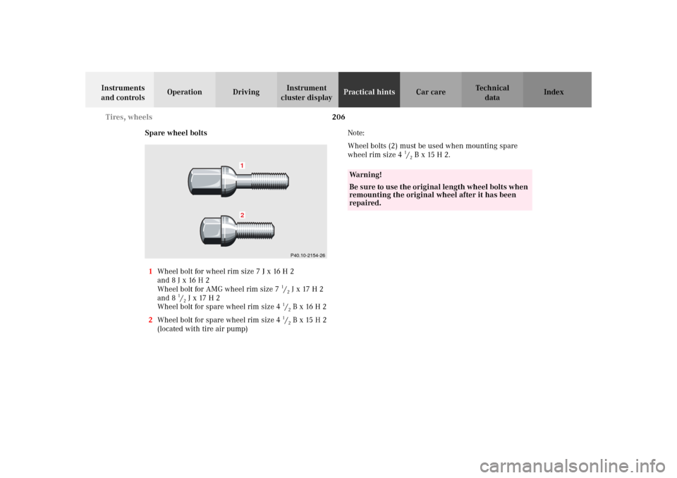
Spare wheel bolts
1Wheel bolt for wheel rim size 7 J x 16 H 2
and 8 J x 16 H 2
Wheel bolt for AMG wheel rim size 7
1/2 J x 17 H 2
and 8
1/2 J x 17 H 2
Wheel bolt for spare wheel rim size 4
1/2 B x 16 H 2
2Wheel bolt for spare wheel rim size 4
1/2 B x 15 H 2
(located with tire air pump)Note:
Wheel bolts (2) must be used when mounting spare
wheel rim size 4
1/2 B x 15 H 2.
21
P40.10-2154-26
Wa r n i n g !
Be sure to use the original length wheel bolts when
remounting the original wheel after it has been
repaired.
Page 213 of 290

210 Tires, wheels
Te ch n i c a l
data Instruments
and controlsOperation DrivingInstrument
cluster displayPractical hintsCar care Index
Important!
For ease of handling and proper unfolding of tire during
its inflation when installing spare wheel with
collapsible tire, first mount the spare wheel, then inflate
the tire.
10. Clean contact surfaces of wheel and wheel hub.
Install wheel on wheel hub. Insert proper wheel
bolts and tighten them snugly.
Unscrew the alignment pin (4) to install the last
wheel bolt.
11. Inflate collapsible spare tire. (See next page for
detailed instructions).Important!
When installing spare wheel with collapsible tire, make
certain to use the correct wheel bolts, supplied in the
vehicle tool kit.
To avoid paint damage, place wheel flat against hub and
hold it there while installing first wheel bolt.
12. Lower vehicle. Remove jack and insert jack tube
cover.