Page 105 of 430

102 Steering wheel adjustment
Te ch n i c a l
data Instruments
and controlsOperationDrivingInstrument
cluster displayPractical hints Car care Index
Steering wheel adjustment
To adjust the steering wheel position, turn the electronic
key in starter switch to position 1 or 2. With the driver’s
door open, the steering wheel can also be operated with
the electronic key removed or in starter switch
position 0. However any adjustment will be cancelled
and the steering wheel will return to it’s position stored
in memory if the driver’s door is closed or the electronic
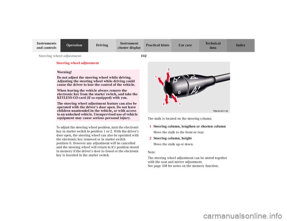
key is inserted in the starter switch.The stalk is located on the steering column.
1Steering column, lengthen or shorten column
Move the stalk to the front or rear.
2Steering column, height
Move the stalk up or down.
Note:
The steering wheel adjustment can be stored together
with the seat and mirror adjustment.
See page 108 for notes on the memory function.
Wa r n i n g !
Do not adjust the steering wheel while driving.
Adjusting the steering wheel while driving could
cause the driver to lose the control of the vehicle.When leaving the vehicle always remove the
electronic key from the starter switch, and take the
KEYLESS-GO-card (if so equipped) with you. The steering wheel adjustment feature can also be
operated with the driver’s door open. Do not leave
children unattended in the vehicle, or with access
to an unlocked vehicle. Unsupervised use of vehicle
equipment may cause serious personal injury.
P68.00-2011-26
1
1
2
2
Page 113 of 430

110 Memory function
Te ch n i c a l
data Instruments
and controlsOperationDrivingInstrument
cluster displayPractical hints Car care Index
Important!
Prior to operating the vehicle, the driver should check
and adjust if necessary the seat height, seat position
fore and aft, and backrest angle to insure adequate
control, reach and comfort. The head restraint should
also be adjusted for proper height. See also airbag
section for proper seat positioning.
In addition, also adjust the steering wheel to ensure
adequate control, reach, operation and comfort. Both the
inside and outside rear view mirrors should be adjusted
for adequate rearward vision.
Fasten seat belts. Infants and small children should be
seated in a properly secured restraint system that
complies with U.S. Federal Motor Vehicle Safety
Standard 213 and Canadian Motor Vehicle Safety
Standard 213.
All seat, head restraint, steering wheel, and rear view
mirror adjustments as well as fastening of seat belts
should be done before the vehicle is put into motion.
Wa r n i n g !
Children 12 years old and under must never ride in
the front seat, except in a Mercedes-Benz
authorized BabySmart
TM compatible child seat,
which operates with the BabySmart
TM system
installed in the vehicle to deactivate the passenger-
side front airbag when it is properly installed.
Otherwise they will be struck by the airbag when it
inflates in a crash. If this happens, serious or fatal
injury can result.
According to accident statistics, children are safer
when properly restrained in the rear seating
positions than in the front seating positions.
Infants and small children must ride in back seats
and be seated in an appropriate infant or child
restraint system, which is properly secured with
the vehicle’s seat belt, fully in accordance with the
child seat manufacturer’s instructions.A child’s risk of serious or fatal injuries is
significantly increased if the child restraints are
not properly secured in the vehicle and the child is
not properly secured in the child restraint.
Page 205 of 430
202 Interior equipment
Te ch n i c a l
data Instruments
and controlsOperationDrivingInstrument
cluster displayPractical hints Car care Index
Cup holder
1Cup holder in front seat armrestTo o p e n :
Fold the cover to the side.
To c l o s e :
Fold the cover back.
P68.00-0769-26
1
Wa r n i n g !
Keep the cup holder closed while traveling. Place
only containers that fit into the cup holder to
prevent spills. Do not fill containers to a height
where the contents could spill during vehicle
maneuvers, especially hot liquids.
Page 206 of 430
203 Interior equipment
Te ch n i c a l
data Instruments
and controlsOperationDrivingInstrument
cluster displayPractical hints Car care Index 2Cup holder in rear seat armrestTo o p e n :
Push front of sliding compartment – the cup holder
slides out.
To c l o s e :
Push the sliding compartment back until it engages.
P91.27-0222-262
Wa r n i n g !
Keep the cup holder closed while traveling. Place
only containers that fit into the cup holder to
prevent spills. Do not fill containers to a height
where the contents could spill during vehicle
maneuvers, especially hot liquids.
Page 288 of 430

285 Driving systems
Te ch n i c a l
data Instruments
and controlsOperationDrivingInstrument
cluster displayPractical hints Car care Index Level control system for vehicles with
Airmatic system
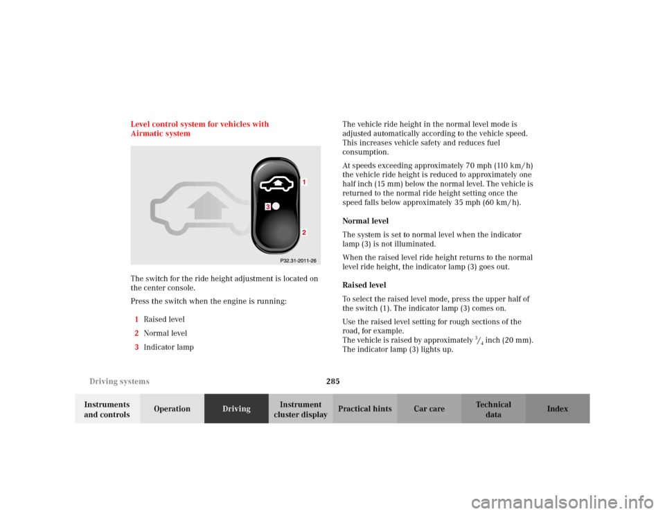
The switch for the ride height adjustment is located on
the center console.
Press the switch when the engine is running:
1Raised level
2Normal level
3Indicator lampThe vehicle ride height in the normal level mode is
adjusted automatically according to the vehicle speed.
This increases vehicle safety and reduces fuel
consumption.
At speeds exceeding approximately 70 mph (110 km / h)
the vehicle ride height is reduced to approximately one
half inch (15 mm) below the normal level. The vehicle is
returned to the normal ride height setting once the
speed falls below approximately 35 mph (60 km / h).
Normal level
The system is set to normal level when the indicator
lamp (3) is not illuminated.
When the raised level ride height returns to the normal
level ride height, the indicator lamp (3) goes out.
Raised level
To select the raised level mode, press the upper half of
the switch (1). The indicator lamp (3) comes on.
Use the raised level setting for rough sections of the
road, for example.
The vehicle is raised by approximately 3/4 inch (20 mm).
The indicator lamp (3) lights up.
Page 290 of 430

287 Driving systems
Te ch n i c a l
data Instruments
and controlsOperationDrivingInstrument
cluster displayPractical hints Car care Index The vehicle chassis ride height is raised or lowered
automatically according to the selected setting and to
the vehicle speed. This helps to increase vehicle
handling safety and lowers fuel consumption.
The selected setting is stored in memory, even with the
electronic key removed from the starter switch.
Note:
See “ACTIVE BODY CONTROL” on page 320 for
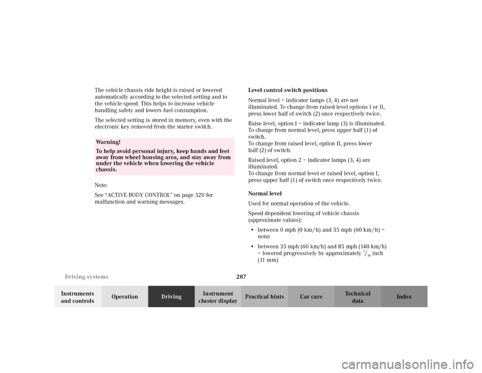
malfunction and warning messages.Level control switch positions
Normal level – indicator lamps (3, 4) are not
illuminated. To change from raised level options I or II,
press lower half of switch (2) once respectively twice.
Raise level, option I – indicator lamp (3) is illuminated.
To change from normal level, press upper half (1) of
switch.
To change from raised level, option II, press lower
half (2) of switch.
Raised level, option 2 – indicator lamps (3, 4) are
illuminated.
To change from normal level or raised level, option I,
press upper half (1) of switch once respectively twice.
Normal level
Used for normal operation of the vehicle.
Speed dependent lowering of vehicle chassis
(approximate values):
•between 0 mph (0 km / h) and 35 mph (60 km / h) –
none
•between 35 mph (60 km/h) and 85 mph (140 km/h)
– lowered progressively by approximately
7/16inch
(11 mm)
Wa r n i n g !
To help avoid personal injury, keep hands and feet
away from wheel housing area, and stay away from
under the vehicle when lowering the vehicle
chassis.
Page 344 of 430
341 Engine compartment
Te ch n i c a l
data Instruments
and controlsOperation DrivingInstrument
cluster displayPractical hintsCar care Index Pull handle (2) to its stop out of radiator grill and open
hood (do not pull up on the handle).
Note:
To avoid damage to the windshield wipers or hood, open
the hood only with the wipers in the parked position. To c l o s e :
Lower the hood and let it drop into lock from a height of
approximately 1 ft. (30 cm), assisting with hands placed
flat on edges of hood (3).
To avoid hood damage, please make sure that hood is
fully closed. If not, repeat closing procedure. Do not
push down on hood to attempt to fully close it.
P88.40-0391-26
2
P88.40-0390-26
3
3
Page 404 of 430
401 Technical data
Te ch n i c a l
data Instruments
and controlsOperation DrivingInstrument
cluster displayPractical hints Car care Index We i g h t s
Main dimensions Roof load max. 220 lb (100 kg)
Trunk load max. 220 lb (100 kg)
Model S 430 (220.070)S 430 (220.170),
S 500 (220.175)S 55 AMG (220.173)S 600 (220.178)
Overall vehicle length 198.3 in (5038 mm) 203.1 in (5158 mm) 203.1 in (5158 mm) 203.1 in (5158 mm)
Overall vehicle width 73.0 in (1855 mm) 73.0 in (1855 mm) 73.0 in (1855 mm) 73.0 in (1855 mm)
Overall vehicle height 57.2 in (1454 mm) 57.2 in (1454 mm) 57.5 in (1460 mm) 57.4 in (1457 mm)
Wheel base 116.7 in (2965 mm) 121.5 in (3085 mm) 121.5 in (3085 mm) 121.5 in (3085 mm)
Track, front 62.0 in (1574 mm) 62.0 in (1574 mm) 62.1 in (1578 mm) 62.0 in (1574 mm)
Track, rear 62.0 in (1574 mm) 62.0 in (1574 mm) 62.0 in (1574 mm) 62.0 in (1574 mm)