2002 MERCEDES-BENZ S500 brake light
[x] Cancel search: brake lightPage 281 of 430
278 Driving systems
Te ch n i c a l
data Instruments
and controlsOperationDrivingInstrument
cluster displayPractical hints Car care Index
Antilock brake system (ABS)
Important!
The ABS improves steering control of the vehicle during
hard braking maneuvers.
The ABS prevents the wheels from locking up above a
vehicle speed of approximately 5 mph (8 km / h)
independent of road surface conditions.At the instant one of the wheels is about to lock up, a
slight pulsation can be felt in the brake pedal,
indicating that the ABS is in the regulating mode. Keep
firm and steady pressure on the brake pedal while
experiencing the pulsation.
Continuous steady brake pedal pressure results in
applying the advantages of the ABS, namely braking
power and ability to steer the vehicle.
In the case of an emergency brake maneuver keep
continuous full pressure on the brake pedal. In this
manner only can the ABS be most effective.
On slippery road surfaces, the ABS will respond even
with light brake pedal pressure because of the
increased likelihood of locking wheels. The pulsating
brake pedal can be an indication of hazardous road
conditions and functions as a reminder to take extra
care while driving.
Wa r n i n g !
Do not pump the brake pedal, rather use firm,
steady brake pedal pressure. Pumping the brake
pedal defeats the purpose for ABS and significantly
reduces braking effectiveness.
Page 302 of 430

299 Check regularly and before a long trip
Te ch n i c a l
data Instruments
and controlsOperationDrivingInstrument
cluster displayPractical hints Car care Index Check regularly and before a long trip 1Windshield washer and
headlamp cleaning system
For refilling reservoir see page 345.
2Coolant level,
see “Adding coolant” on page 344
3Engine oil level,
see “Engine oil level checking” on page 156 and 342
4Brake fluid,
see “Brake fluid” on page 404
Opening hood, see page 339.
Ve h i c l e l i g h t i n g : Check function and cleanliness. For
replacement of light bulbs, see “Exterior lamps” on
page 364.
Exterior lamp switch, see page 158.
Page 304 of 430

301 Contents – Instrument cluster display
Te ch n i c a l
data Instruments
and controlsOperation DrivingInstrument
cluster displayPractical hints Car care Index
Instrument cluster displayMalfunction and indicator
lamps in the
instrument cluster ....................302
On-board diagnostic
system ..........................................302
Check engine malfunction
indicator lamp .............................302
Brake warning lamp ..................304
Supplemental restraint system
(SRS) indicator lamp ..................305
Fuel reserve warning .................305
ABS malfunction
indicator lamp .............................306
Electronic stability program
(ESP) — warning lamp ...............307
Distronic (DTR) –
warning lamp ..............................307
Seat belt nonusage
warning lamp ..............................308Malfunction and indicator
lamp in the
center console ........................... 308
AIRBAG OFF indicator lamp .... 308
Malfunction and warning
messages in the
multifunction display .............. 309
DISPLAY DEFECTIVE ................. 310
BATTERY/ALTERNATOR ........... 311
ENTRANCE POSITION ...............312
BRAKE ASSIST ............................312
BRAKE LINING WEAR ............... 313
BRAKE FLUID ............................. 313
PARKING BRAKE ........................ 314
TRUNK OPEN .............................. 314
ELEC. STABIL. PROG.
(Electronic stability
program) ...................................... 315
COOLANT
(coolant level) .............................. 316
COOLANT
(coolant temperature) ................ 317LIGHTING SYSTEM .................... 318
LIGHT SENSOR ...........................320
ACTIVE BODY CONTROL
(ABC) ............................................320
TIRE PRESSURE .........................322
ENGINE OIL LEVEL ...................324
CRUISE CONTROL .....................325
KEY ...............................................325
DOOR ...........................................326
HOOD ...........................................326
TELE AID .....................................327
CHIP-CARD
(KEYLESS-GO) ............................328
SELECTOR LEVER ......................329
TELEPHONE – FUNCTION .......329
WASHER FLUID .........................330
AIR SPRING (AirMatic) ............. 331
DISTRONIC (DTR) ......................332
AIR CLEANER .............................333
Page 321 of 430
318 Malfunction and warning messages
Te ch n i c a l
data Instruments
and controlsOperation DrivingInstrument
cluster displayPractical hints Car care Index
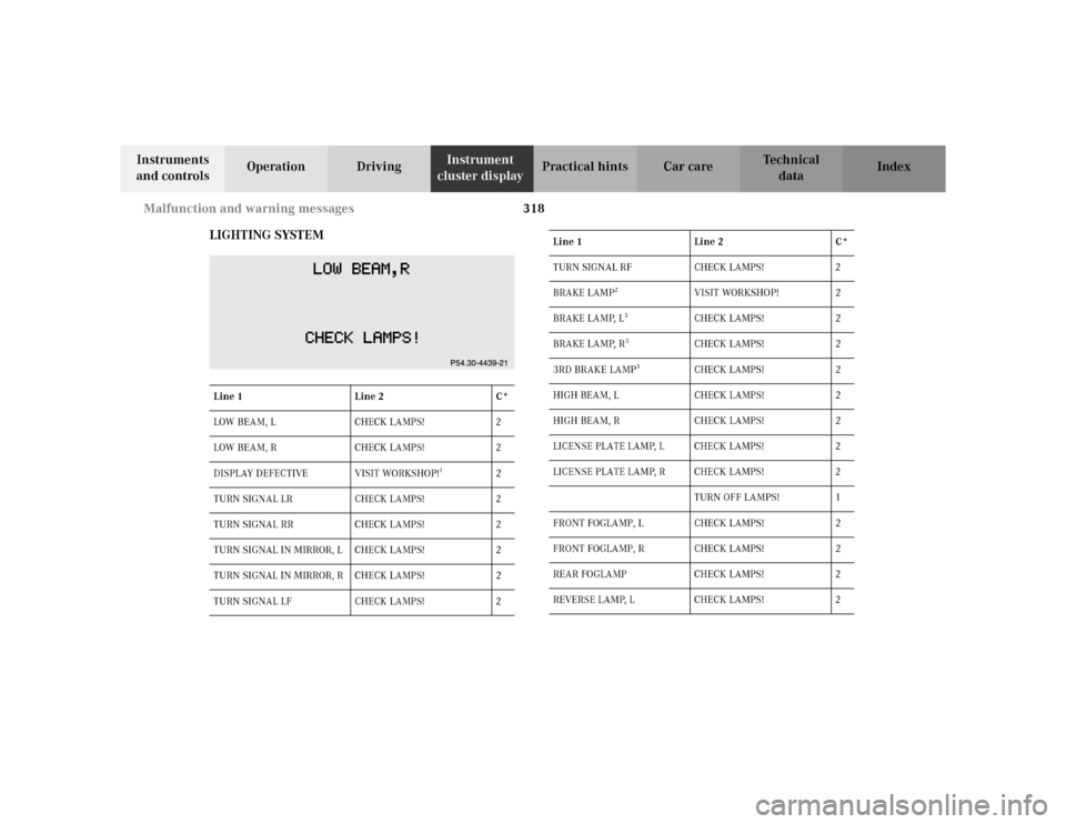
LIGHTING SYSTEM
Line 1 Line 2 C*
LOW BEAM, L CHECK LAMPS! 2
LOW BEAM, R CHECK LAMPS! 2
DISPLAY DEFECTIVE VISIT WORKSHOP!
1
2
TURN SIGNAL LR CHECK LAMPS! 2
TURN SIGNAL RR CHECK LAMPS! 2
TURN SIGNAL IN MIRROR, L CHECK LAMPS! 2
TURN SIGNAL IN MIRROR, R CHECK LAMPS! 2
TURN SIGNAL LF CHECK LAMPS! 2
TURN SIGNAL RF CHECK LAMPS! 2
BRAKE LAMP
2
VISIT WORKSHOP! 2
BRAKE LAMP, L
3
CHECK LAMPS! 2
BRAKE LAMP, R
3
CHECK LAMPS! 2
3RD BRAKE LAMP
3
CHECK LAMPS! 2
HIGH BEAM, L CHECK LAMPS! 2
HIGH BEAM, R CHECK LAMPS! 2
LICENSE PLATE LAMP, L CHECK LAMPS! 2
LICENSE PLATE LAMP, R CHECK LAMPS! 2
TURN OFF LAMPS! 1
FRONT FOGLAMP, L CHECK LAMPS! 2
FRONT FOGLAMP, R CHECK LAMPS! 2
REAR FOGLAMP CHECK LAMPS! 2
REVERSE LAMP, L CHECK LAMPS! 2 Line 1 Line 2 C*
Page 322 of 430
319 Malfunction and warning messages
Te ch n i c a l
data Instruments
and controlsOperation DrivingInstrument
cluster displayPractical hints Car care IndexIn the case of bulb failures in certain lamps, other lamps
will substitute. See page 364 for instructions on
replacing bulbs.
* C = Category, see page 309
LR: left rear; LF: left front
RR: right rear; RF: right front
1 The display or the system is malfunctioning.
2 The brake lamps are switching on after a delay or are permanently
on – visit workshop immediately.
3 The brake lamps comprise several light emitting diodes. The
warning message will only appear if all light emitting diodes have
stopped working.
4 Other bulbs will be brought into use as replacements when certain
lamps blow. REVERSE LAMP, R CHECK LAMPS! 2
TAIL LAMP, L CHECK LAMPS!
SUBSTITUTE LAMP ON!
4
2
TAIL LAMP, R CHECK LAMPS!
SUBSTITUTE LAMP ON!
4
2
STANDING LAMP, L CHECK LAMPS!
SUBSTITUTE LAMP ON!
4
2
STANDING LAMP, R CHECK LAMPS!
SUBSTITUTE LAMP ON!
4
2 Line 1 Line 2 C*
Page 340 of 430

337 Fuses
Te ch n i c a l
data Instruments
and controlsOperation DrivingInstrument
cluster displayPractical hintsCar care Index Fuses
Most of your vehicle’s electrical components are fused
with safety fuses. With the exception of the brake lights,
all individual lighting system components are
electronically fused. Before replacing a blown safety
fuse, determine the cause of the short circuit. Always
observe amperage and color of fuse.
The circuit for components is protected by a cycled
circuit breaker interrupted if too much current is being
drawn. The circuit closes automatically after a short
time; the circuit is broken again if the malfunction
reoccurs.
Always use a new fuse for replacement. Never attempt to
repair or bridge a blown fuse.
A fuse chart, spare fuses and a fuse extractor are located
in the vehicle tool kit in the luggage bowl under the
trunk floor. See page 346 for notes on the vehicle tool
kit.Fuse boxes in the engine compartment
1Fuse box in engine compartment, left-hand side
3Ta b s
3
3
1
P54.15-2007-26
Page 363 of 430
360 Jump starting
Te ch n i c a l
data Instruments
and controlsOperation DrivingInstrument
cluster displayPractical hintsCar care Index
Proceed as follows:
1. Position the vehicle with the charged battery so that
the jumper cables will reach, but never let the
vehicles touch. Make sure the jumper cables do not
have loose or missing insulation.
2. On both vehicles:
•Turn off engine and all lights and accessories,
except hazard warning flashers or work lights.
•Apply parking brake and shift selector lever to
position “P”.
Important!
3. Clamp one end of the first jumper cable to the
positive (+) terminal of the discharged battery and
the other end to the positive (+) terminal of the
charged battery. Make sure the cable clamps do not
touch any other metal parts.
4. Clamp one end of the second jumper cable to the
grounded negative (–) terminal of the charged
battery and the final connection to the negative (–)
under hood terminal of the disabled vehicle.Important!
5. Start engine of the vehicle with the charged battery
and run at high idle. Make sure the cables are not
on or near pulleys, fans, or other parts that move
when the engine is started. Allow the discharged
battery to charge for a few minutes. Start engine of
the disabled vehicle in the usual manner.
6. After the engine has started, remove jumper cables
by exactly reversing the above installation
sequence, starting with the last connection made
first. When removing each clamp, make sure that it
does not touch any other metal while the other end
is still attached.
Note:
If engine does not run after several unsuccessful
starting attempts, have it checked at the nearest
authorized Mercedes-Benz Center.
Excessive unburned fuel may damage the catalytic
converter.
Page 420 of 430
417 Index
Te ch n i c a l
data Instruments
and controlsOperation DrivingInstrument
cluster displayPractical hints Car careIndex
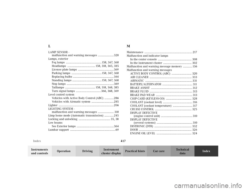
LLAMP SENSOR -
malfunction and warning messages ......................320
Lamps, exterior
Fog lamps ..................................................158, 367, 368
Headlamps ....................................... 158, 318, 365, 385
License plate lamps .................................................. 369
Parking lamps ..........................................158, 367, 368
Replacing bulbs ......................................................... 364
Standing lamps .........................................158, 367, 368
Stop lamps ..................................................................369
Taillamps .......................................... 158, 318, 368, 385
Turn signal lamps ................................... 366, 368, 369
Level control system
Vehicles with Active Body Control (ABC) ............. 286
Vehicles with Airmatic system ............................... 285
Lighter .............................................................................206
LIGHTING SYSTEM -
malfunction and warning messages ...................... 318
Limp home mode (Automatic transmission) ............. 245
Locking and unlocking ............................................ 35, 38
Low beams
See Exterior lamps ....................................................364
Lumbar support ............................................................... 69
MMaintenance ................................................................... 217
Malfunction and indicator lamps
In the center console ............................................... 308
In the instrument cluster ........................................ 302
Malfunction and warning message memory ............. 136
Malfunction and warning messages
ACTIVE BODY CONTROL (ABC) ............................ 320
AIR CLEANER ........................................................... 333
AIRMATIC ..................................................................331
BATTERY/ALTERNATOR .......................................... 311
BRAKE ASSIST .......................................................... 312
BRAKE FLUID ............................................................ 313
BRAKE PAD WEAR ................................................... 313
CHIP-CARD (KEYLESS-GO) .................................... 328
COOLANT (coolant level) ......................................... 316
COOLANT (coolant temperature) ........................... 317
CRUISE CONTROL ................................................... 325
DISPLAY DEFECTIVE
(engine control unit) ............................................ 310
DISPLAY DEFECTIVE
(several systems) .................................................. 310
DISTRONIC (DTR) .................................................... 332
DOOR .......................................................................... 326
ENGINE OIL LEVEL ................................................. 324