2002 MERCEDES-BENZ S500 spare
[x] Cancel search: sparePage 8 of 430

5 ContentsCoolant level ...................................344
Adding coolant ...........................344
Windshield and headlamp
washer system ...........................345
Windshield and headlamp
washer fluid mixing ratio .........345
Spare wheel, vehicle tools,
storage compartment ................346
Vehicle jack .....................................347
Wheels .............................................348
Tire Replacement .......................348
Rotating wheels ..........................349
Spare wheel ....................................349
Changing wheels ........................... 351
Tire inflation pressure ..................356
Battery .............................................357
Jump starting ..................................359
Towing the vehicle ......................... 361
Exterior lamps ................................364
Headlamp assembly ...................365
Taillamp assemblies ..................368Changing batteries in
the electronic key ......................371
Synchronizing
remote control ............................ 373
Changing batteries in the
KEYLESS-GO-card .....................374
Emergency engine
shut-down ...................................376
Fuel filler flap,
manual release ..........................376
Emergency operation of
sliding/pop-up roof .................. 377
Replacing wiper blades ................ 378
Roof rack ......................................... 380
Vehicle careCleaning and care
of the vehicle ............................. 382
Power washer ............................. 383
Tar stains .................................... 384
Paintwork, painted body
components ................................ 384Engine cleaning ..........................384
Vehicle washing .........................384
Ornamental moldings ................385
Headlamps, taillamps,
turn signal lenses ......................385
Cleaning the Distronic
system sensor .............................386
Cleaning the parktronic
system sensors ...........................386
Wiper blades ...............................387
Light alloy wheels ......................388
Instrument cluster .....................388
Steering wheel and
gear selector lever ......................388
Cup holder ...................................388
Seat belts .....................................389
Headliner and shelf
below rear window .....................389
Leather upholstery .....................389
Hard plastic trim items .............389
Plastic and rubber parts ............389
Page 9 of 430

6 Contents
Technical dataSpare parts service ........................392
Warranty coverage .........................392
Identification labels .......................393
Layout of poly-V-belt drive ............395
Technical data ................................396
Fuels, coolants, lubricants etc. -
capacities ...................................402Engine oils ...................................... 404
Engine oil additives ...................... 404
Air conditioner refrigerant .......... 404
Brake fluid ...................................... 404
Premium unleaded gasoline ........ 405
Fuel requirements ........................ 405
Gasoline additives ......................... 406
Coolants .......................................... 406
Consumer information ................. 408
IndexIndex ................................................ 410
Page 158 of 430

155 Tire inflation pressure monitor
Te ch n i c a l
data Instruments
and controlsOperationDrivingInstrument
cluster displayPractical hints Car care Index Notes:
To ensure proper functioning of the tire inflation
pressure monitor, the tire inflation pressure should be
checked and corrected according to the label affixed
inside the fuel filler flap. For a detailed description,
refer to page 356.
The message “REACTIVATE – TIRE PRESS. MONITOR”
appears if the tire inflation pressure shows an increase
of 4.4 psi (0.3 bar) or more. Reactivate the tire inflation
pressure monitor.
The tire inflation pressure monitor only functions on
wheels equipped with the proper electronic sensors.
Inquire at your authorized Mercedes-Benz Center about
retrofitting other than original Mercedes-Benz wheels
with electronic sensors.
Transporting a deflated road wheel in the vehicle, e.g.
after having a flat, the tire inflation pressure monitor
should only be activated once the flat tire and rim are
removed from the vehicle.To prevent possible damage to the electronic sensors,
have tire changes only performed at an authorized
Mercedes-Benz Center.
For malfunction and warning messages, see page 309.
When checking the tire inflation pressure of the road
wheels, also check the spare tire.
The tire inflation pressure of the spare wheel, mounted
or not mounted, is not monitored by the tire inflation
pressure monitor.
See page 346 for location of the spare wheel, and
page 356 for tire inflation pressure.
Page 217 of 430

214 Infrared reflecting windshield
Te ch n i c a l
data Instruments
and controlsOperationDrivingInstrument
cluster displayPractical hints Car care Index
Infrared reflecting windshield
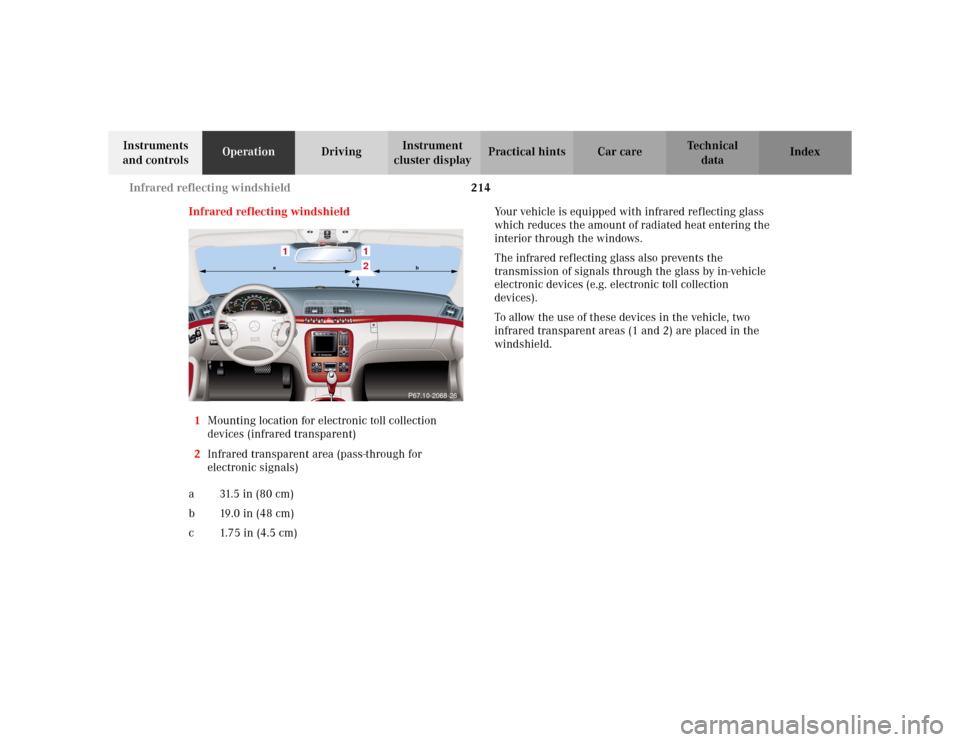
1Mounting location for electronic toll collection
devices (infrared transparent)
2Infrared transparent area (pass-through for
electronic signals)
a 31. 5 i n ( 8 0 c m )
b19.0in (48cm)
c 1.75 in (4.5 cm)Your vehicle is equipped with infrared reflecting glass
which reduces the amount of radiated heat entering the
interior through the windows.
The infrared reflecting glass also prevents the
transmission of signals through the glass by in-vehicle
electronic devices (e.g. electronic toll collection
devices).
To allow the use of these devices in the vehicle, two
infrared transparent areas (1 and 2) are placed in the
windshield.
1
12
P67.10-2068-26
ab
c
Page 225 of 430

222 Tele Aid
Te ch n i c a l
data Instruments
and controlsOperationDrivingInstrument
cluster displayPractical hints Car care Index
Roadside Assistance button •
Located below the center armrest cover is the Roadside
Assistance button•. Pressing and holding the
button (for longer than 2 seconds) will initiate a call to a
Mercedes-Benz Roadside Assistance dispatcher. The
button will flash while the call is in progress. The
message “ROADSIDE ASSISTANCE – CONNECTING
CALL” will appear in the multifunction display. When
the connection is established, the message “ROADSIDE
ASSISTANCE – CALL CONNECTED” appears in the
multifunction display. The Tele Aid system will transmit
data generating the vehicle identification number,
model, color and location (subject to availability of
cellular and GPS signals).A voice connection between the Roadside Assistance
dispatcher and the occupants of the vehicle will be
established. When a voice connection is established the
audio system mutes and the message “TELE AID –
ROADSIDE ASSISTANCE CALL ACTIVE” appears in the
multifunction display. The nature of the need for
assistance can then be described. The Mercedes-Benz
Roadside assistance dispatcher will either dispatch a
qualified Mercedes-Benz technician or arrange to tow
your vehicle to the nearest Mercedes-Benz Center. For
services such as labor and/or towing charges may apply.
Refer to the Roadside Assistance manual for more
information.
These programs are only available in the USA:
•Sign and Drive services: Services such as jump start,
a few gallons of fuel or the replacement of a flat tire
with the vehicle spare tire are obtainable,
•Remote Vehicle Diagnostics: This function permits
the Mercedes-Benz Roadside Assistance dispatcher
to download malfunction codes and actual vehicle
data.
Wa r n i n g !
If you feel at any way in jeopardy when in the
vehicle (e.g. smoke or fire in the vehicle, vehicle in
a dangerous road location), please do not wait for
voice contact after you have pressed the emergency
button. Carefully leave the vehicle and move to a
safe location. The Response Center will
automatically contact local emergency officials
with the vehicle’s approximate location if they
receive an automatic “SOS” signal and cannot make
voice contact with the vehicle occupants.
Page 284 of 430

281 Driving systems
Te ch n i c a l
data Instruments
and controlsOperationDrivingInstrument
cluster displayPractical hints Car care Index Notes:
The yellow ESP warning lampv in the speedometer
dial comes on with the electronic key in starter switch
position 2. It should go out with the engine running.
If the ESP warning message is displayed, a malfunction
has been detected in the system. Only partial engine
output will be available.
Have the ESP checked at your authorized
Mercedes-Benz Center as soon as possible.
For ESP warning message, see page 307.
With the ABS malfunctioning, the ESP is also switched
off.
Driving the vehicle with varied size tires will cause the
wheels to rotate at different speeds, therefore the ESP
may activate (yellow ESP warning lamp in speedometer
dial comes on). For this reason, all wheels, including the
spare wheel, must have the same tire size. When testing the parking brake on a brake test
dynamometer, the engine must be shut off. Otherwise,
the ESP will immediately be engaged and will apply the
rear wheel brakes.
In winter operation, the maximum effectiveness of the
ESP is only achieved with Mercedes-Benz recommended
M+S rated radial-ply tires and / or snow chains.
Synchronizing ESP
If the power supply was interrupted (battery
disconnected or empty), the ESP warning message may
be displayed with the engine running.
Turn steering wheel completely to the left and then to
the right. The ESP warning message should go out.
Page 338 of 430

335 Contents – Practical hints
Te ch n i c a l
data Instruments
and controlsOperation DrivingInstrument
cluster displayPractical hintsCar care Index
Practical hintsFirst aid kit .....................................336
Stowing things in the vehicle ......336
Fuses ................................................337
Hood .................................................339
Checking engine oil level .............342
Automatic transmission
fluid level ...................................343
Active body control (ABC)
fluid level ...................................343
Coolant level ...................................344
Adding coolant ...........................344
Windshield and headlamp
washer system ...........................345
Windshield and headlamp
washer fluid mixing ratio .........345Spare wheel, vehicle tools,
storage compartment ............... 346
Vehicle jack .................................... 347
Wheels ............................................ 348
Tire Replacement ....................... 348
Rotating wheels ......................... 349
Spare wheel .................................... 349
Changing wheels ........................... 351
Tire inflation pressure ................. 356
Battery ............................................. 357
Jump starting ................................. 359
Towing the vehicle ........................ 361
Exterior lamps ............................... 364
Headlamp assembly .................. 365
Taillamp assemblies .................. 368Changing batteries in
the electronic key ..................... 371
Synchronizing
remote control ............................373
Changing batteries in the
KEYLESS-GO-card ..................... 374
Emergency engine
shut-down .................................. 376
Fuel filler flap,
manual release .......................... 376
Emergency operation of
sliding/pop-up roof ...................377
Replacing wiper blades .................378
Roof rack .........................................380
Page 340 of 430

337 Fuses
Te ch n i c a l
data Instruments
and controlsOperation DrivingInstrument
cluster displayPractical hintsCar care Index Fuses
Most of your vehicle’s electrical components are fused
with safety fuses. With the exception of the brake lights,
all individual lighting system components are
electronically fused. Before replacing a blown safety
fuse, determine the cause of the short circuit. Always
observe amperage and color of fuse.
The circuit for components is protected by a cycled
circuit breaker interrupted if too much current is being
drawn. The circuit closes automatically after a short
time; the circuit is broken again if the malfunction
reoccurs.
Always use a new fuse for replacement. Never attempt to
repair or bridge a blown fuse.
A fuse chart, spare fuses and a fuse extractor are located
in the vehicle tool kit in the luggage bowl under the
trunk floor. See page 346 for notes on the vehicle tool
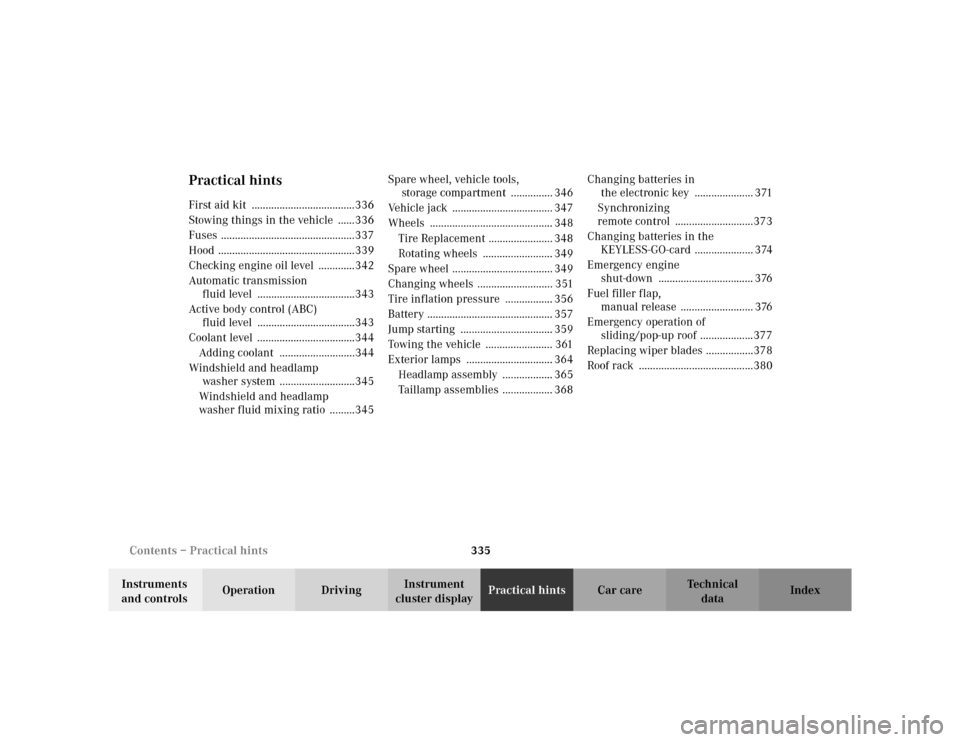
kit.Fuse boxes in the engine compartment
1Fuse box in engine compartment, left-hand side
3Ta b s
3
3
1
P54.15-2007-26