2002 MERCEDES-BENZ ML320 steering
[x] Cancel search: steeringPage 169 of 342
166 Tele Aid
Te ch n i c a l
data Instruments
and controlsOperationDrivingInstrument
cluster displayPractical hints Car care Index
Tele Aid (optional for Canada)
Important!
The initial activation of the Tele Aid system may only be
performed by completing the subscriber agreement and
placing an acquaintance call using the “SOS” button.
Failure to complete either of these steps will result in a
system that is not activated. If the system is not
activated the indicator lamp in the “SOS” button stays
on after turning electronic key in starter switch to
position 2 and the message “TELE AID – NOT
ACTIVATED” will be shown in the MCS display for
approx. 10 seconds.
If you have any questions regarding activation, please
call the Response Center at 1-800-756-9018 (in the USA)
or 1-888-923-8367 (in Canada).
(Te l ematic Alarm Identification on Demand)
The Tele Aid system consists of three types of response;
automatic and manual emergency, roadside assistance
and information.The Tele Aid system is operational providing that the
vehicle’s battery is charged, properly connected, not
damaged and cellular and GPS coverage is available.
The speaker volume of a Tele Aid call can be adjusted
using the volume control on the MCS unit. To activate,
press the “SOS” button, the Roadside Assistance
button• or the Information button¡, depending
on the type of response required.
Shortly after the completion of your Acquaintance Call,
you will receive a user ID and password via first call
mail. By visiting www.mbusa.com and selecting
“Tele Aid” (USA only), you will have access to account
information, remote door unlock, Info Services
* profile
and more.
* OptionalSystem self-check
Initially, after turning the key in steering lock to
position 2, malfunctions are detected and indicated (the
indicator lamps in the “SOS” button, the Roadside
Assistance button• and Information button¡
stay on longer than 10 seconds or do not come on). The
message “TELE AID – PLEASE VISIT WORKSHOP”
appears in the MCS display.
Page 174 of 342
171 Tele Aid
Te ch n i c a l
data Instruments
and controlsOperationDrivingInstrument
cluster displayPractical hints Car care Index When the connection is established, the message
“ROADSIDE ASSISTANCE – CALL CONNECTED”
appears in the MCS display. The Tele Aid system will
transmit data generating the vehicle identification
number, model, color and location (subject to
availability of cellular and GPS signals).
While the call is connected, you can change to
navigation menu by pressing NAVI button on the MCS.
A voice connection between the Roadside Assistance
dispatcher and the occupants of the vehicle will be
established. When a voice connection is established the
audio system mutes and the message “TELE AID –
ROADSIDE ASSISTANCE CALL ACTIVE” appears in the
MCS display. The nature of the need for assistance can
then be described. The Mercedes-Benz Roadside
assistance dispatcher will either dispatch a qualified
Mercedes-Benz technician or arrange to tow your
vehicle to the nearest Mercedes-Benz Center. For
services such as labor and/or towing charges may apply.
Refer to the Roadside Assistance manual for more
information.These programs are only available in the USA:
•Sign and Drive services: Services such as jump start,
a few gallons of fuel or the replacement of a flat tire
with the vehicle spare tire are obtainable,
•Remote Vehicle Diagnostics: This function permits
the Mercedes-Benz Roadside Assistance dispatcher
to download malfunction codes and actual vehicle
data.
Notes:
The indicator lamp in the Roadside Assistance
button• remains illuminated in red for
approximately 10 seconds during the system self-check
after turning key in steering lock to position 2 (together
with the “SOS” button and the Information
button¡).
See system self-check on page 166 when the indicator
lamp does not light up in red or stay on longer than
approximately 10 seconds.
Page 176 of 342
173 Tele Aid
Te ch n i c a l
data Instruments
and controlsOperationDrivingInstrument
cluster displayPractical hints Car care Index The Tele Aid system will transmit data generating the
vehicle identification number, model, color and location
(subject to availability of cellular and GPS signals).
While the call is connected, you can change to
navigation menu by pressing NAVI button on the MCS.
A voice connection between the Customer Assistance
Center representative and the occupants of the vehicle
will be established. When a voice connection is
established, the audio system mutes and the message
“TELE AID – INFO CALL ACTIVE” appears in the MCS
display. Information regarding the operation of your
vehicle, the nearest Mercedes-Benz Light Truck Center
or Mercedes-Benz USA products and services is
available to you.
For more details concerning Tele Aid, please visit
www.mbusa.com and use your ID and password, sent to
you separately, to learn more (USA only).Notes:
The indicator lamp in the Information button¡
remains illuminated in red for approximately
10 seconds during the system self-check after turning
key in steering lock to position 2 (together with the
“SOS” button and the Roadside Assistance button•).
See system self-check on page 166 when the indicator
lamps do not light up in red or stay on longer than
approximately 10 seconds.
If the indicator lamp in the Information button¡ is
illuminated continuously and there was no voice
connection to the Response Center established, then the
Tele Aid system could not initiate an Roadside
Assistance call (e.g. the relevant cellular phone network
is not available). The message “Info – CALL FAILED”
appears in the MCS display.
Should this occur, information must be summoned by
other means.
Information calls can be terminated using the END
button on the MCS unit.
Page 183 of 342
180 Steering lock
Te ch n i c a l
data Instruments
and controlsOperationDrivingInstrument
cluster displayPractical hints Car care Index
Steering lock
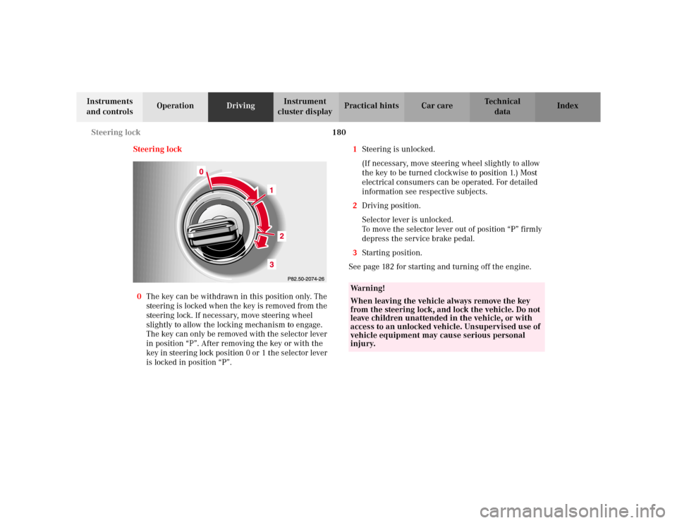
0The key can be withdrawn in this position only. The
steering is locked when the key is removed from the
steering lock. If necessary, move steering wheel
slightly to allow the locking mechanism to engage.
The key can only be removed with the selector lever
in position “P”. After removing the key or with the
key in steering lock position 0 or 1 the selector lever
is locked in position “P”.1Steering is unlocked.
(If necessary, move steering wheel slightly to allow
the key to be turned clockwise to position 1.) Most
electrical consumers can be operated. For detailed
information see respective subjects.
2Driving position.
Selector lever is unlocked.
To move the selector lever out of position “P” firmly
depress the service brake pedal.
3Starting position.
See page 182 for starting and turning off the engine.
Wa r n i n g !
When leaving the vehicle always remove the key
from the steering lock, and lock the vehicle. Do not
leave children unattended in the vehicle, or with
access to an unlocked vehicle. Unsupervised use of
vehicle equipment may cause serious personal
injury.
Page 184 of 342
181 Steering lock
Te ch n i c a l
data Instruments
and controlsOperationDrivingInstrument
cluster displayPractical hints Car care Index Caution!
To prevent accelerated battery discharge and a possible
dead battery, always remove the key from the steering
lock. Do not leave the key in steering lock position 0.
Notes:
A warning sounds when the driver’s door is opened
while the key is in steering lock position 1 or 0.
With the engine at idle speed, the charging rate of the
alternator (output) is limited.It is therefore recommended that you turn off
unnecessary electrical consumers while driving in stop-
and-go traffic. This precaution helps to avoid draining of
the battery.
Unnecessary strain on the battery and charging system
may be minimized by turning off the following power
consumers, for example: Heated seats, rear window
defroster.
Page 185 of 342

182 Starting and turning off the engine
Te ch n i c a l
data Instruments
and controlsOperationDrivingInstrument
cluster displayPractical hints Car care Index
Starting and turning off the engine
Before starting
Ensure that parking brake is engaged and that selector
lever is in position “P” or “N”.
Important!
In areas where temperatures frequently drop below -4
°F
(-20
°C) we recommend that an engine block heater be
installed. Your authorized Mercedes-Benz Light Truck
Center will advise you on this subject.
Starting
Do not depress accelerator.
Turn key in steering lock to position 2. Briefly turn key
in steering lock clockwise to the stop and release. The
starter will engage until the engine is running.
If engine will not run, and the starting procedure stops,
turn key completely to the left and repeat starting the
engine.
After several unsuccessful attempts, have the system
checked at the nearest authorized Mercedes-Benz Light
Truck Center.A starting procedure can be interrupted by turning the
key to steering lock position 0.
Important!
Due to the installed starter non-repeat feature, the key
must be turned completely to the left before attempting
to start the engine again.
Note:
In case the engine cannot be started and the
messagesÁ and î are shown in the odometer
display field, the system is not operational. Contact an
authorized Mercedes-Benz Light Truck Center or call
1-800-FOR-MERCedes (in the USA), or 1-800-387-0100
(in Canada).
Turning off
Put the selector lever in position “P” and turn the key in
the steering lock to position 0 to stop the engine.
The key can only be removed with the selector lever in
position “P”.
Page 188 of 342
185 Automatic transmission
Te ch n i c a l
data Instruments
and controlsOperationDrivingInstrument
cluster displayPractical hints Car care Index Maneuvering
To maneuver in tight areas, e.g. when pulling into a
parking space, control the vehicle speed by gradually
releasing the brakes. Accelerate gently and never
abruptly step on the accelerator.
To rock a vehicle out of soft ground (mud or snow),
alternately shift from forward to reverse, while applying
slight partial throttle.
Rocking a vehicle free in this manner may cause the
ABS or traction system malfunction indicator lamp to
come on. Turn off and restart the engine to clear the
malfunction indication.Towing a trailer
If the transmission hunts between gears on inclines,
manually shift to a lower gear (select “4”, “3”, “2”
or “1”). A lower gear and reduction of speed reduces the
chance of engine overloading and / or overheating.
At very steep inclines, not manageable with selector
lever in position “1”, switch transfer case to LOW
RANGE, see page 227 for instructions on how to engage
LOW RANGE.
For instructions on trailer towing refer to page 209.
Wa r n i n g !
Getting out of your vehicle with the selector lever
not fully engaged in position “P” is dangerous.
Also, when parked on an incline, position “P” alone
may not prevent your vehicle from moving,
possibly hitting people or objects.Always set the parking brake in addition to shifting
to position “P”, see page 191 for parking brake. When parked on an incline, also turn front wheel
against curb.
Wa r n i n g !
When leaving the vehicle always remove the key
from the steering lock, and lock the vehicle. Do not
leave children unattended in the vehicle, or with
access to an unlocked vehicle. Children could move
the gear selector lever from position “P”, which
could result in an accident or serious injury.
Page 189 of 342
186 Automatic transmission
Te ch n i c a l
data Instruments
and controlsOperationDrivingInstrument
cluster displayPractical hints Car care Index
Selector lever position
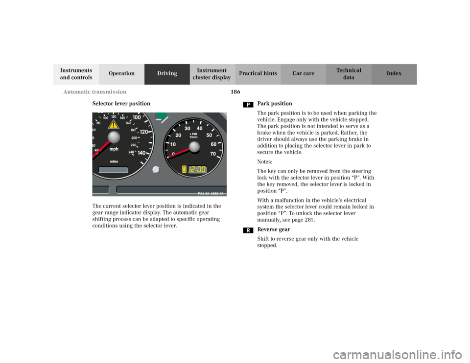
The current selector lever position is indicated in the
gear range indicator display. The automatic gear
shifting process can be adapted to specific operating
conditions using the selector lever.Park position
The park position is to be used when parking the
vehicle. Engage only with the vehicle stopped.
The park position is not intended to serve as a
brake when the vehicle is parked. Rather, the
driver should always use the parking brake in
addition to placing the selector lever in park to
secure the vehicle.
Notes:
The key can only be removed from the steering
lock with the selector lever in position “P”. With
the key removed, the selector lever is locked in
position “P”.
With a malfunction in the vehicle’s electrical
system the selector lever could remain locked in
position “P”. To unlock the selector lever
manually, see page 281.
Reverse gear
Shift to reverse gear only with the vehicle
stopped.