2002 MERCEDES-BENZ ML320 towing
[x] Cancel search: towingPage 252 of 342
249 Contents - Practical hints
Te ch n i c a l
data Instruments
and controlsOperation DrivingInstrument
cluster displayPractical hintsCar care Index
Practical hintsFirst aid kit .....................................250
Fuses ................................................250
Electrical outlet ..............................252
Stowing items in the vehicle ........252
Hood .................................................253
Checking engine oil level .............255
Automatic transmission
fluid level ...................................256
Engine oil consumption ................256
Coolant level ...................................256
Adding coolant ...........................257
Windshield washer/headlamp
cleaning system .........................258
Windshield and headlamp
washer fluid mixing ratio .........259Ve h i c l e j a c k ,
wheel bolt wrench and
screwdriver ............................... 259
Air pump ......................................... 261
Wheels ............................................ 262
Tire replacement ....................... 262
Rotating wheels ......................... 263
Spare wheel .................................... 264
Changing wheels ........................... 267
Tire inflation pressure ................. 272
Battery ............................................. 273
Jump starting ................................. 275
Towing the vehicle ........................ 277
Transmission selector lever,
manually unlocking .................. 281
Stranded vehicle ............................ 281Exterior lamps ................................282
Headlamp assembly ...................283
Taillamp assemblies ..................287
Adjusting headlamp aim ...............290
Remote control battery
replacement ...............................292
Synchronizing
remote control ............................293
Emergency operation of
sliding/pop-up roof ...................294
Manual release for
fuel filler flap .............................295
Replacing wiper blades .................295
Roof rack .........................................296
Page 255 of 342
252 Electrical outlet
Te ch n i c a l
data Instruments
and controlsOperation DrivingInstrument
cluster displayPractical hintsCar care Index
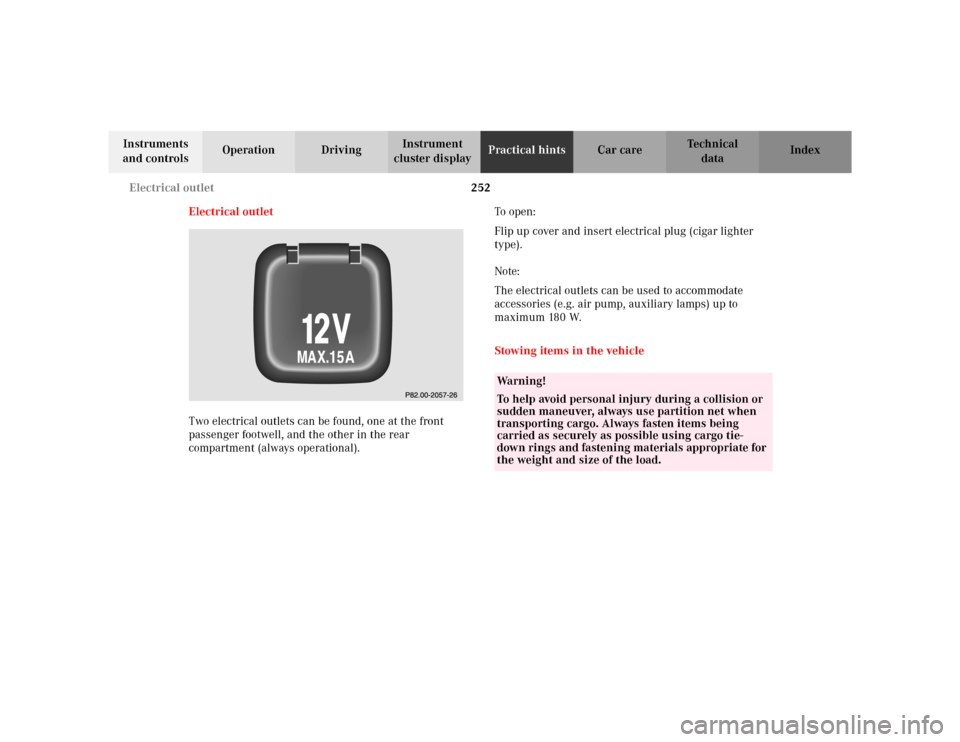
Electrical outlet
Two electrical outlets can be found, one at the front
passenger footwell, and the other in the rear
compartment (always operational).To o p e n :
Flip up cover and insert electrical plug (cigar lighter
type).
Note:
The electrical outlets can be used to accommodate
accessories (e.g. air pump, auxiliary lamps) up to
maximum 180 W.
Stowing items in the vehicle
Wa r n i n g !
To help avoid personal injury during a collision or
sudden maneuver, always use partition net when
transporting cargo. Always fasten items being
carried as securely as possible using cargo tie-
down rings and fastening materials appropriate for
the weight and size of the load.
Page 280 of 342
277 Towing
Te ch n i c a l
data Instruments
and controlsOperation DrivingInstrument
cluster displayPractical hintsCar care Index Towing the vehicle
Important!
When towing the vehicle, please, note the following:
With the automatic central locking activated and the
engine running, the vehicle doors lock if the left front
wheel is turning at vehicle speeds of approximately
9 mph (15 km / h) or more.
To prevent the vehicle door locks from locking,
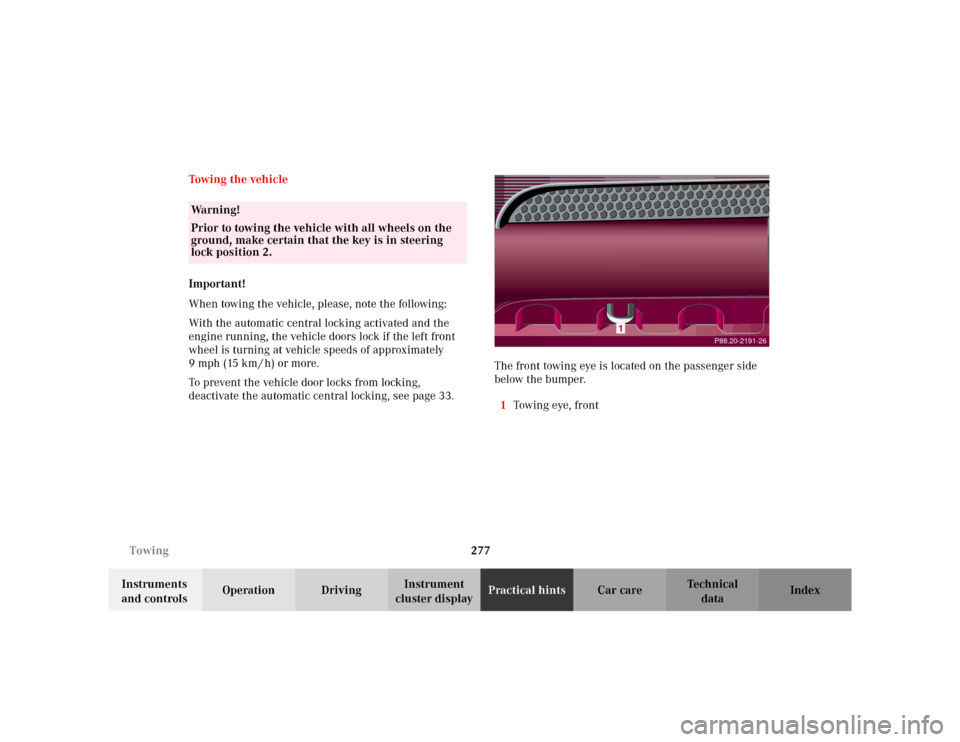
deactivate the automatic central locking, see page 33.The front towing eye is located on the passenger side
below the bumper.
1Towin g eye, fr on t
Wa r n i n g !
Prior to towing the vehicle with all wheels on the
ground, make certain that the key is in steering
lock position 2.
P88.20-2191-26
Page 281 of 342
278 Towing
Te ch n i c a l
data Instruments
and controlsOperation DrivingInstrument
cluster displayPractical hintsCar care Index
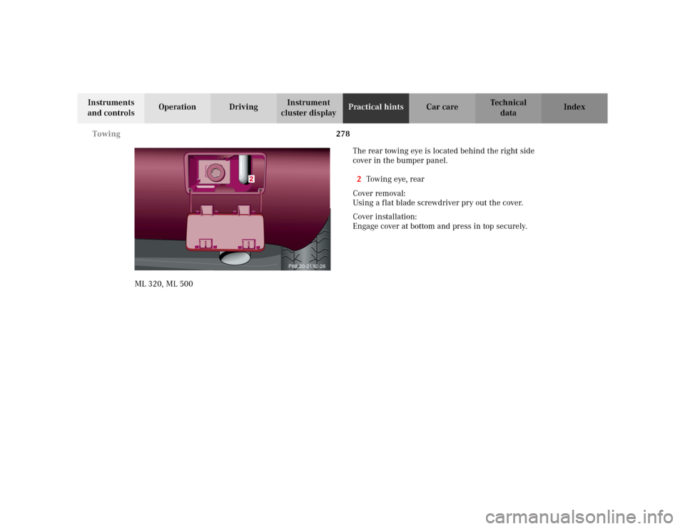
ML 320, ML 500The rear towing eye is located behind the right side
cover in the bumper panel.
2Towin g eye, rea r
Cover removal:
Using a flat blade screwdriver pry out the cover.
Cover installation:
Engage cover at bottom and press in top securely.
P88.20-2192-26
Page 282 of 342
279 Towing
Te ch n i c a l
data Instruments
and controlsOperation DrivingInstrument
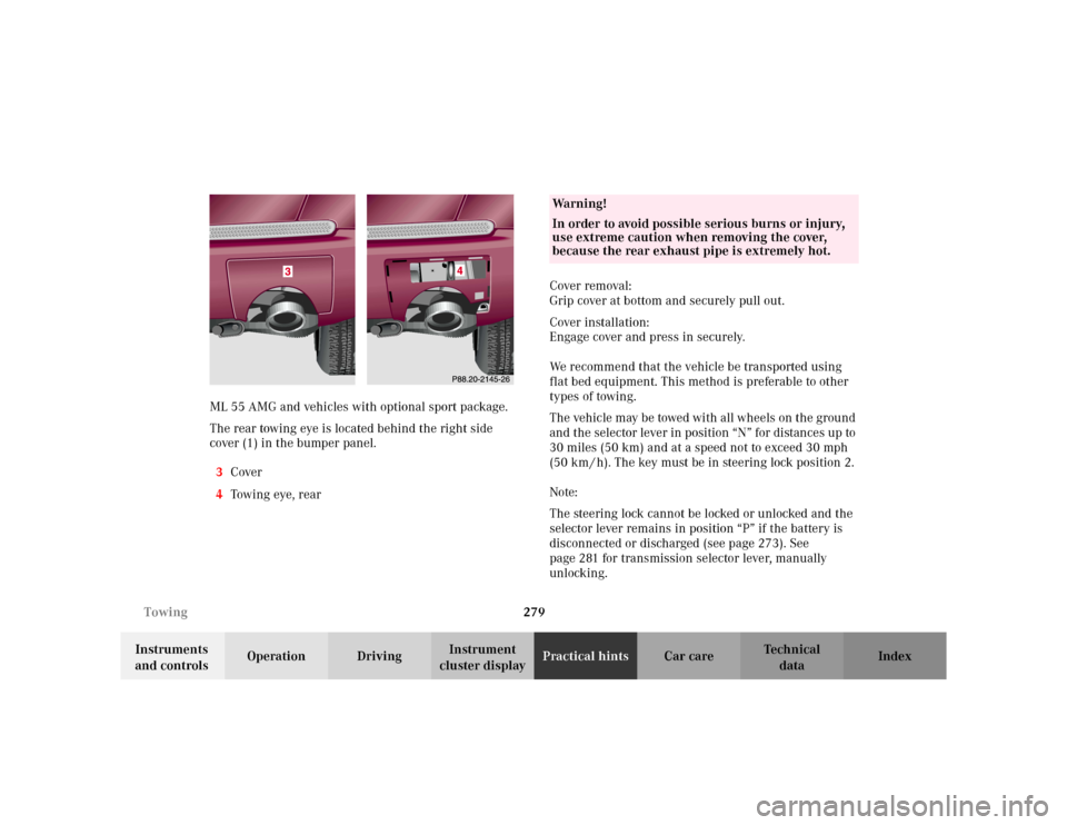
cluster displayPractical hintsCar care Index ML 55 AMG and vehicles with optional sport package.
The rear towing eye is located behind the right side
cover (1) in the bumper panel.
3Cover
4Tow i n g eye , r e a rCover removal:
Grip cover at bottom and securely pull out.
Cover installation:
Engage cover and press in securely.
We recommend that the vehicle be transported using
flat bed equipment. This method is preferable to other
types of towing.
The vehicle may be towed with all wheels on the ground
and the selector lever in position “N” for distances up to
30 miles (50 km) and at a speed not to exceed 30 mph
(50 km / h). The key must be in steering lock position 2.
Note:
The steering lock cannot be locked or unlocked and the
selector lever remains in position “P” if the battery is
disconnected or discharged (see page 273). See
page 281 for transmission selector lever, manually
unlocking.
Wa r n i n g !
In order to avoid possible serious burns or injury,
use extreme caution when removing the cover,
because the rear exhaust pipe is extremely hot.
Page 283 of 342
280 Towing
Te ch n i c a l
data Instruments
and controlsOperation DrivingInstrument
cluster displayPractical hintsCar care Index
To be certain to avoid additional damage to the vehicle
powertrain, however you should do the following:
•With damage to front axle, raise front axle. Remove
flexible drive shaft between rear axle and transfer
case
•With damage to rear axle, raise rear axle and tow
vehicle with wheel lift or dolly placed under front
wheels.
•With damage to transfer case, remove flexible drive
shafts to the drive axles.
Note:
Always install new self-locking nuts when reinstalling
the flexible drive shaft.Caution!
If the vehicle is towed with the front axle raised, the
engine must be shut off (key in steering lock position 1).
Otherwise, the 4-ETS+ may become engaged which may
cause loss of towing control. Switch off the tow-away
alarm (see page 37) as well as the ESP (see page 225).
Note:
To signal turns while being towed with hazard warning
flasher in use, turn key in steering lock to position 2
and activate combination switch for left or right turn
signal in usual manner. Now deactivate the hazard
warning flasher, only the selected turn signal will
operate. Upon canceling the turn signal, the hazard
warning flasher must be activated again.
Wa r n i n g !
With the engine not running, there is no power
assistance for the braking and steering systems. In
this case, it is important to keep in mind that a
considerably higher degree of effort is necessary to
brake and steer the vehicle.
Page 284 of 342
281 Towing
Te ch n i c a l
data Instruments
and controlsOperation DrivingInstrument
cluster displayPractical hintsCar care Index Transmission selector lever, manually unlocking
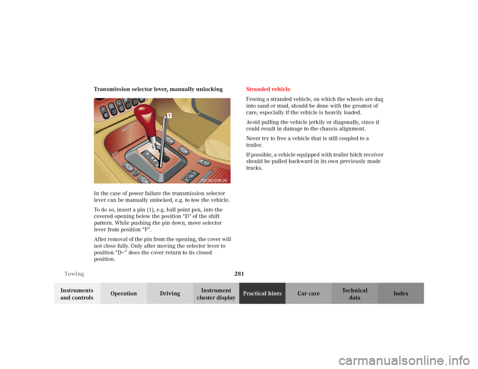
In the case of power failure the transmission selector
lever can be manually unlocked, e.g. to tow the vehicle.
To do so, insert a pin (1), e.g. ball point pen, into the
covered opening below the position “D” of the shift
pattern. While pushing the pin down, move selector
lever from position “P”.
After removal of the pin from the opening, the cover will
not close fully. Only after moving the selector lever to
position “D–” does the cover return to its closed
position.Stranded vehicle
Freeing a stranded vehicle, on which the wheels are dug
into sand or mud, should be done with the greatest of
care, especially if the vehicle is heavily loaded.
Avoid pulling the vehicle jerkily or diagonally, since it
could result in damage to the chassis alignment.
Never try to free a vehicle that is still coupled to a
trailer.
If possible, a vehicle equipped with trailer hitch receiver
should be pulled backward in its own previously made
tracks.
P27.60-2186-26
1
Page 335 of 342
332 Index
Te ch n i c a l
data Instruments
and controlsOperation DrivingInstrument
cluster displayPractical hints Car careIndex
Snow chains .................................................................... 199
SOS-call
See Tele Aid ............................................................... 166
Space-saver tire
Air pump .................................................................... 261
Spare parts service ........................................................ 306
Spare wheel .................................................................... 264
Space-saver tire ......................................................... 265
Split rear seat bench ..................................................... 139
Easy entry/exit feature ............................................ 142
Rear seat head restraints ......................................... 143
SRS indicator lamp ........................................................ 242
SRS malfunction .............................................................. 60
Start lock-out .................................................................... 25
Starting and turning off the engine ............................ 182
Steering lock ................................................................... 180
Steering wheel
Adjustable .................................................................... 74
Indicator lamp ...........................................................244
Stop lamp, high mounted ............................................. 289
Storage compartments
Center console ........................................................... 133
Compartment under front passenger seat ............ 134
Glove box .................................................................... 133
Storing mirror positions ................................................. 78
Stowing items in the vehicle ........................................252Stranded vehicle .............................................................281
Sun visors ........................................................................ 131
Supplemental restraint system (SRS) ........................... 56
Synchronizing remote control .................................... 293
TTachometer ........................................................................ 88
Technical data ................................................................ 309
Electrical system ....................................................... 312
Main dimensions ...................................................... 313
Rims and tires ................................................... 310, 311
Weights ....................................................................... 312
Tele Aid ............................................................................ 166
Emergency calls ........................................................ 167
Information ................................................................ 172
Initiating an emergency call manually .................. 169
Roadside Assistance ................................................. 170
Telephone, general ......................................................... 157
Telephones and two-way radios ................................... 164
Telescoping steering column
Adjusting ...................................................................... 74
Indicator lamp .......................................................... 244
The first 1 000 miles (1 500 km) ................................ 165
Third row seats ............................................................... 144