2002 MERCEDES-BENZ ML320 Stored
[x] Cancel search: StoredPage 46 of 342
43 Seats
Te ch n i c a l
data Instruments
and controlsOperationDrivingInstrument
cluster displayPractical hints Car care Index Memory function
(optional; Canada only: standard on ML 500;
USA: standard on ML 55 AMG)
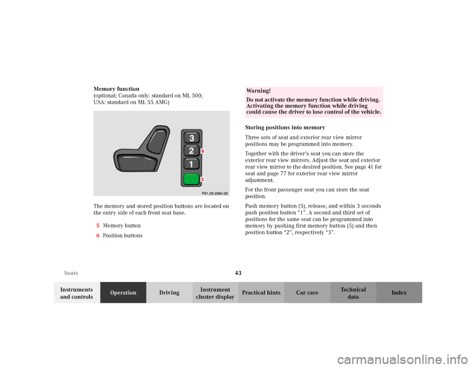
The memory and stored position buttons are located on
the entry side of each front seat base.
5Memory button
6Position buttonsStoring positions into memory
Three sets of seat and exterior rear view mirror
positions may be programmed into memory.
Together with the driver’s seat you can store the
exterior rear view mirrors. Adjust the seat and exterior
rear view mirror to the desired position. See page 41 for
seat and page 77 for exterior rear view mirror
adjustment.
For the front passenger seat you can store the seat
position.
Push memory button (5), release, and within 3 seconds
push position button “1”. A second and third set of
positions for the same seat can be programmed into
memory by pushing first memory button (5) and then
position button “2”, respectively “3”.
Wa r n i n g !
Do not activate the memory function while driving.
Activating the memory function while driving
could cause the driver to lose control of the vehicle.
Page 81 of 342
78 Rear view mirrors
Te ch n i c a l
data Instruments
and controlsOperationDrivingInstrument
cluster displayPractical hints Car care Index
Storing exterior rear view mirror positions
(only vehicle with memory function)
The exterior rear view mirror positions are stored in
memory with the seat positions and can be recalled
when necessary. See page 43 for notes on the memory
function.
Parking position (only vehicle with memory function)
The passenger side exterior mirror can be adjusted and
programmed to assist the driver during parking
maneuvers (e.g. to observe the curb or other objects
close to the vehicle).
With the key in steering lock position 2, and the exterior
rear view mirror switch in the passenger side position,
the passenger side mirror will be turned downward
when placing the gear selector lever in “R” reverse.
The passenger side mirror will return to its previous
position:
•immediately at speeds above approx. 6 mph
(10 km/h) – independent of the engaged gear,
•after 10 seconds when shifting gear selector lever
from “R” Reverse,
•by pressing the driver’s side mirror button%.To store passenger side mirror parking position:
1. The vehicle must be stationary.
Turn key to steering lock position 1 or 2.
2. Select passenger side mirror& and adjust the
mirror to view the curb.
3. Push the memory button “M”, see page 43.
4. Within 3 seconds push bottom of adjustment
button (3), see page 77.
The mirror should not move.
Repeat the memory procedure if the mirror moves.
Note:
The selected position will be stored relative to the
memory button (1, 2, 3) pushed.
Page 127 of 342
124 Interior equipment
Te ch n i c a l
data Instruments
and controlsOperationDrivingInstrument
cluster displayPractical hints Car care Index
Blocking of rear door window operation
If no operation of the rear door windows by the
switches (6) and (7), located on rear center console (for
instance by children) is desired, slide override
switch (5) to right, symbolN becomes visible.
Note:
After turning off the engine, the power windows can be
operated for approximately 30 minutes or until a front
door is opened.Synchronizing power windows
Resynchronize the power windows, if
•the power supply was interrupted (battery
disconnected or low),
•the windows cannot be opened or closed by the
express feature.
To r e s y n ch r o n i z e :
Turn key in steering lock to position 2.
Press j side of power window switch until the
window is completely closed and hold down for
approximately 1 second. Repeat procedure for each
window.
The automatic full opening and closing procedure of the
windows should now be restored.
Wa r n i n g !
When leaving the vehicle, always remove the key
from the steering lock, and lock the vehicle. Do not
leave children unattended in the vehicle, or with
access to an unlocked vehicle. Unsupervised use of
vehicle equipment can cause serious personal
injury.
Page 135 of 342
132 Interior equipment
Te ch n i c a l
data Instruments
and controlsOperationDrivingInstrument
cluster displayPractical hints Car care Index
Interior Storage compartments, armrest and cup holder
Wa r n i n g !
To help avoid personal injury during a collision or
sudden maneuver, exercise care when stowing
things. Put luggage or cargo in the rear cargo area
and secure. Do not pile luggage or cargo higher
than the seat backs. Luggage nets cannot secure hard or heavy objects.
Wa r n i n g !
Keep compartment lids closed. This will help to
prevent stored objects from being thrown about
and injuring vehicle occupants during an accident
and sudden maneuvers.
Page 142 of 342
139 Interior equipment
Te ch n i c a l
data Instruments
and controlsOperationDrivingInstrument
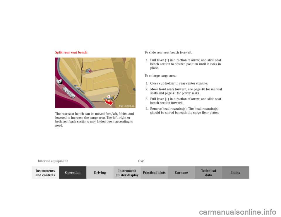
cluster displayPractical hints Car care Index Split rear seat bench
The rear seat bench can be moved fore / aft, folded and
lowered to increase the cargo area. The left, right or
both seat back sections may folded down according to
need.To slide rear seat bench fore / aft:
1. Pull lever (1) in direction of arrow, and slide seat
bench section to desired position until it locks in
place.
To enlarge cargo area:
1. Close cup holder in rear center console.
2. Move front seats forward, see page 40 for manual
seats and page 41 for power seats.
3. Pull lever (1) in direction of arrow, and slide seat
bench section forward.
4. Remove head restraint(s). The head restraint(s)
should be stored beneath the cargo floor plates.
Page 146 of 342
143 Interior equipment
Te ch n i c a l
data Instruments
and controlsOperationDrivingInstrument
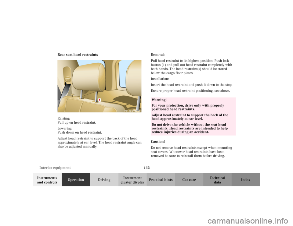
cluster displayPractical hints Car care Index Rear seat head restraints
Raising:
Pull up on head restraint.
Lowering:
Push down on head restraint.
Adjust head restraint to support the back of the head
approximately at ear level. The head restraint angle can
also be adjusted manually.Removal:
Pull head restraint to its highest position. Push lock
button (1) and pull out head restraint completely with
both hands. The head restraint(s) should be stored
below the cargo floor plates.
Installation:
Insert the head restraint and push it down to the stop.
Ensure proper head restraint positioning, see above.
Caution!
Do not remove head restraints except when mounting
seat covers. Whenever head restraints have been
removed be sure to reinstall them before driving.
Wa r n i n g !
For your protection, drive only with properly
positioned head restraints.Adjust head restraint to support the back of the
head approximately at ear level.Do not drive the vehicle without the seat head
restraints. Head restraints are intended to help
reduce injuries during an accident.
Page 195 of 342
192 Driving instructions
Te ch n i c a l
data Instruments
and controlsOperationDrivingInstrument
cluster displayPractical hints Car care Index
Driving instructions
Drive sensibly – save fuel
Fuel consumption, to a great extent, depends on driving
habits and operating conditions.
To save fuel you should:
•keep tires at the recommended inflation pressures,
•remove unnecessary loads,
•remove roof rack when not in use,
•allow engine to warm up under low load use,
•avoid frequent acceleration and deceleration,
•have all maintenance work performed at regular
intervals by an authorized Mercedes-Benz Light
Truck Center.
Fuel consumption is also increased by driving in cold
weather, in stop-and-go traffic, on short trips and in hilly
country.Drinking and driving
Ped al s
Wa r n i n g !
Drinking or taking drugs and driving can be a very
dangerous combination. Even a small amount of
alcohol or drugs can affect your reflexes,
perceptions and judgement.The possibility of a serious or even fatal accident is
sharply increased when you drink or take drugs
and drive.Please don’t drink or take drugs and drive or allow
anyone to drive after drinking or taking drugs.Wa r n i n g !
Keep driver’s foot area clear at all times. Objects
stored in this area may impair pedal movement.
Page 243 of 342
240 Malfunction and indicator lamps
Te ch n i c a l
data Instruments
and controlsOperation DrivingInstrument
cluster displayPractical hints Car care Index
Malfunction and indicator lamps
in the instrument cluster
General information:
If a bulb in the instrument cluster fails to light up
during the bulb self-check when turning the key in
steering lock to position 2, have it checked and replaced
if necessary.
On-board diagnostic system
Check engine malfunction indicator lamp
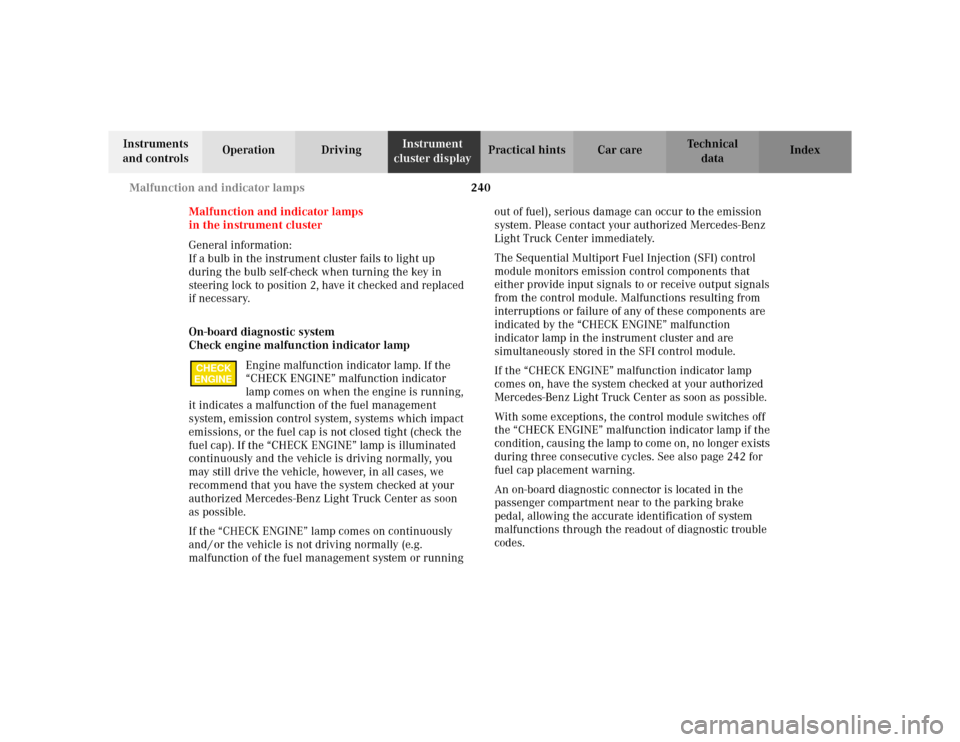
Engine malfunction indicator lamp. If the
“CHECK ENGINE” malfunction indicator
lamp comes on when the engine is running,
it indicates a malfunction of the fuel management
system, emission control system, systems which impact
emissions, or the fuel cap is not closed tight (check the
fuel cap). If the “CHECK ENGINE” lamp is illuminated
continuously and the vehicle is driving normally, you
may still drive the vehicle, however, in all cases, we
recommend that you have the system checked at your
authorized Mercedes-Benz Light Truck Center as soon
as possible.
If the “CHECK ENGINE” lamp comes on continuously
and / or the vehicle is not driving normally (e.g.
malfunction of the fuel management system or running out of fuel), serious damage can occur to the emission
system. Please contact your authorized Mercedes-Benz
Light Truck Center immediately.
The Sequential Multiport Fuel Injection (SFI) control
module monitors emission control components that
either provide input signals to or receive output signals
from the control module. Malfunctions resulting from
interruptions or failure of any of these components are
indicated by the “CHECK ENGINE” malfunction
indicator lamp in the instrument cluster and are
simultaneously stored in the SFI control module.
If the “CHECK ENGINE” malfunction indicator lamp
comes on, have the system checked at your authorized
Mercedes-Benz Light Truck Center as soon as possible.
With some exceptions, the control module switches off
the “CHECK ENGINE” malfunction indicator lamp if the
condition, causing the lamp to come on, no longer exists
during three consecutive cycles. See also page 242 for
fuel cap placement warning.
An on-board diagnostic connector is located in the
passenger compartment near to the parking brake
pedal, allowing the accurate identification of system
malfunctions through the readout of diagnostic trouble
codes.
CHECK
ENGINE