Page 294 of 385
291 Malfunction and warning messages
Te ch n i c a l
data Instruments
and controlsOperation DrivingInstrument
cluster displayPractical hints Car care Index ELECTRONIC BRAKE BOOSTER (EBB)
* C = Category, see page 272.
ENGINE AIR FILTER* C = Category, see page 272.
1 The engine air filter is clogged and must be replaced. Line 1 Line 2 C*
ELECTRIC BRAKE BOOSTER VISIT WORKSHOP! 2Line 1 Line 2 C*
ENGINE AIR FILTER
1
VISIT WORKSHOP! 2
J_G463.book Seite 291 Mittwoch, 19. September 2001 8:06 08
Page 295 of 385
292 Malfunction and warning messages
Te ch n i c a l
data Instruments
and controlsOperation DrivingInstrument
cluster displayPractical hints Car care Index
TC SHIFT
* C = Category, see page 272.The shift process in the transfer case was cancelled
because of a malfunction. See page 248 for switching
the transfer case.TC SHIFT CONDITIONS
* C = Category, see page 272.The shift conditions for a selection process in the
transfer case have not been met. See page 248 for
switching the transfer case.
Line 1 Line 2 C*
TC S HIF T C A N C EL LED 2
Line 1 Line 2 C*
TC SHIFT CONDITIONS NOT FULFILLED 2
J_G463.book Seite 292 Mittwoch, 19. September 2001 8:06 08
Page 296 of 385
293 Malfunction and warning messages
Te ch n i c a l
data Instruments
and controlsOperation DrivingInstrument
cluster displayPractical hints Car care Index TC IN NEUTRAL
* C = Category, see page 272.No gear has been selected in the transfer case, it is in
“NEUTRAL”. Engage transfer case to gear position
“HIGH” or “LOW”, see page 248 for switching the
transfer case.TRANSFER CASE
* C = Category, see page 272.There is a malfunction in the transfer case. Have the
transfer case checked immediately by a Mercedes-Benz
Light Truck Center.
Line 1 Line 2 C*
TC IN NEUTRAL 3Wa r n i n g !
If TC is in neutral, the “P” position of transmission
will not hold vehicle. The parking brake must be
applied to hold vehicle in place.
Line 1 Line 2 C*
TRANSFER CASE VISIT WORKSHOP 2
J_G463.book Seite 293 Mittwoch, 19. September 2001 8:06 08
Page 307 of 385
304 Engine compartment
Te ch n i c a l
data Instruments
and controlsOperation DrivingInstrument
cluster displayPractical hintsCar care Index
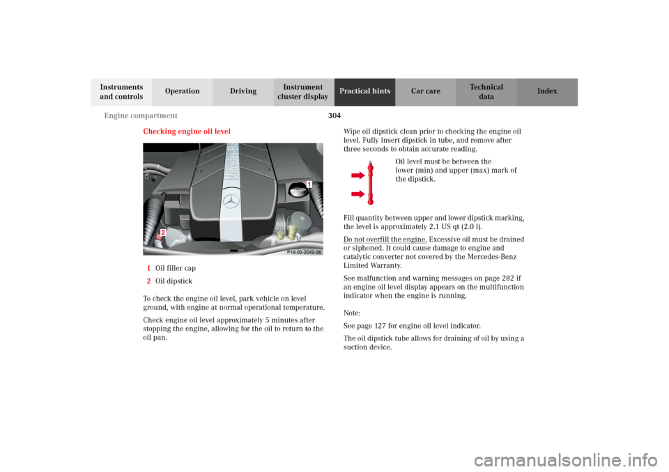
Checking engine oil level
1Oil filler cap
2Oil dipstick
To check the engine oil level, park vehicle on level
ground, with engine at normal operational temperature.
Check engine oil level approximately 5 minutes after
stopping the engine, allowing for the oil to return to the
oil pan.Wipe oil dipstick clean prior to checking the engine oil
level. Fully insert dipstick in tube, and remove after
three seconds to obtain accurate reading.
Oil level must be between the
lower (min) and upper (max) mark of
the dipstick.
Fil l q u a n t it y b e twe e n up p e r a n d l owe r d ip stick m a r k in g ,
the level is approximately 2.1 US qt (2.0 l).
Do not overfill the engine.
Excessive oil must be drained
or siphoned. It could cause damage to engine and
catalytic converter not covered by the Mercedes-Benz
Limited Warranty.
See malfunction and warning messages on page 282 if
an engine oil level display appears on the multifunction
indicator when the engine is running.
Note:
See page 127 for engine oil level indicator.
The oil dipstick tube allows for draining of oil by using a
suction device.
J_G463.book Seite 304 Mittwoch, 19. September 2001 8:06 08
Page 318 of 385
315 Tires, Wheels
Te ch n i c a l
data Instruments
and controlsOperation DrivingInstrument
cluster displayPractical hintsCar care Index Move vehicle to a level area which is a safe distance
from the roadway.
Important!
The vehic le door s lock if t he lef t f ron t wheel r otate s with
the engine running. Do not leave the engine running
while changing a wheel.
1. Set parking brake and turn on hazard warning
flasher.
2. Move selector lever to position “P” and turn off
engine, and remove key from the starter switch.
Lock steering wheel with wheels in straight ahead
position.
3. Prevent vehicle from rolling away by blocking
wheels with wheel chocks (not supplied with
vehicle) or sizable wood block or stone. When
changing a wheel on a hill, place chocks on the
downhill side blocking both wheels of the other
axle. On a level road, place one chock in front of and
one behind the wheel that is diagonally opposite to
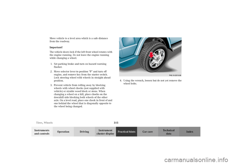
the wheel being changed.4. Using the wrench, loosen but do not yet remove the
wheel bolts.
J_G463.book Seite 315 Mittwoch, 19. September 2001 8:06 08
Page 325 of 385
322 Jump starting
Te ch n i c a l
data Instruments
and controlsOperation DrivingInstrument
cluster displayPractical hintsCar care Index
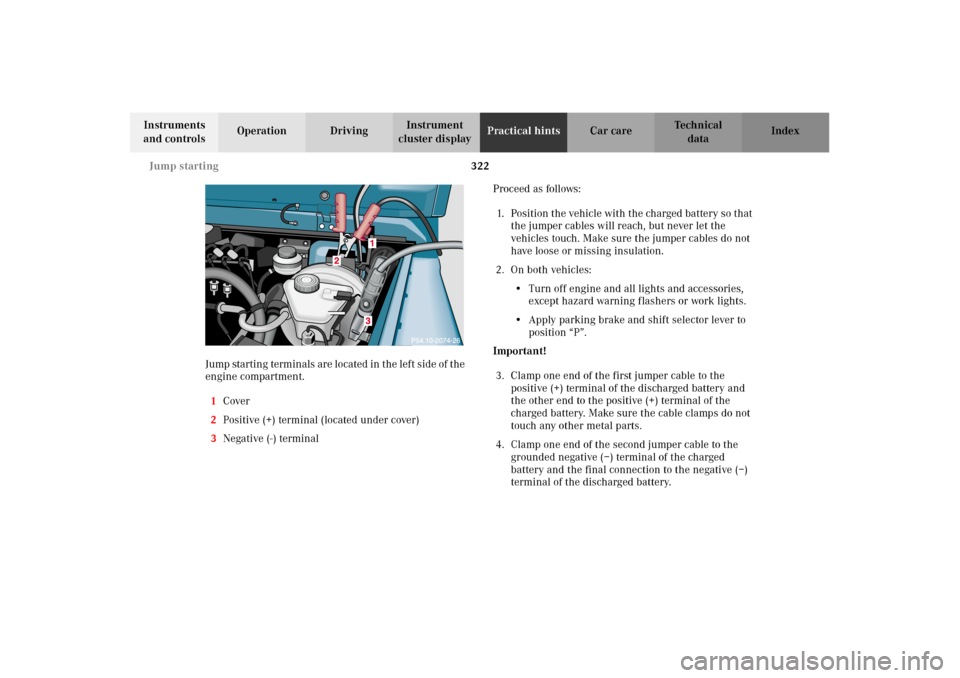
Jump startin g term in als ar e located in t he lef t s id e of t he
engine compartment.
1Cover
2Positive (+) terminal (located under cover)
3Negative (-) terminalProceed as follows:
1. Position the vehicle with the charged battery so that
the jumper cables will reach, but never let the
vehicles touch. Make sure the jumper cables do not
have loose or missing insulation.
2. On both vehicles:
•Turn off engine and all lights and accessories,
except hazard warning flashers or work lights.
•Apply parking brake and shift selector lever to
position “P”.
Important!
3. Clamp one end of the first jumper cable to the
positive (+) terminal of the discharged battery and
the other end to the positive (+) terminal of the
charged battery. Make sure the cable clamps do not
touch any other metal parts.
4. Clamp one end of the second jumper cable to the
grounded negative (–) terminal of the charged
battery and the final connection to the negative (–)
terminal of the discharged battery.
J_G463.book Seite 322 Mittwoch, 19. September 2001 8:06 08
Page 329 of 385
326 Towing
Te ch n i c a l
data Instruments
and controlsOperation DrivingInstrument
cluster displayPractical hintsCar care Index
Engine damage /Transmission damage,
Electrical malfunction
To be certain to avoid additional damage to the vehicle
powertrain, however you should do the following:
Shift automatic transmission to position “N”.
Important!
Vehicle may be towed for distances up to 30 miles
(50 km) and at a speed not to exceed 30 mph
(50 km/h).
For towing vehicle for distances exceeding 30 miles
(50 km) or if the vehicle has a damaged transfer
case, remove drive shafts to the drive axles.
When towing vehicle with one axle raised, the
electronic key in starter switch must be in
position 1.
With damage to front axle, raise front axle. Remove
drive shaft between rear axle and transfer case.
With damage to rear axle, raise rear axle and tow
vehicle with wheel lift or dolly placed under front
wheels.Notes:
When removing drive shaft, place M10 nuts on bolts as
distance sleeves and tighten using M8 nuts.
Always install new self-locking nuts when reinstalling
the drive shaft.
Caution!
If the vehicle is towed with the front axle raised, the
engine must be shut off (electronic key in starter switch
position 1). Otherwise, the 4-ETS may become engaged
which may cause loss of towing control. Switch off the
tow-away alarm (see page 43) as well as the ESP (see
page 245).
Note:
To signal turns while being towed with hazard warning
flasher in use, turn electronic key in starter switch to
position 1 and activate combination switch for left or
right turn signal in usual manner. Now deactivate the
hazard warning flasher, only the selected turn signal
will operate. Upon canceling the turn signal, the hazard
warning flasher must be activated again.
J_G463.book Seite 326 Mittwoch, 19. September 2001 8:06 08
Page 372 of 385
369 Index
Te ch n i c a l
data Instruments
and controlsOperation DrivingInstrument
cluster displayPractical hints Car careIndex
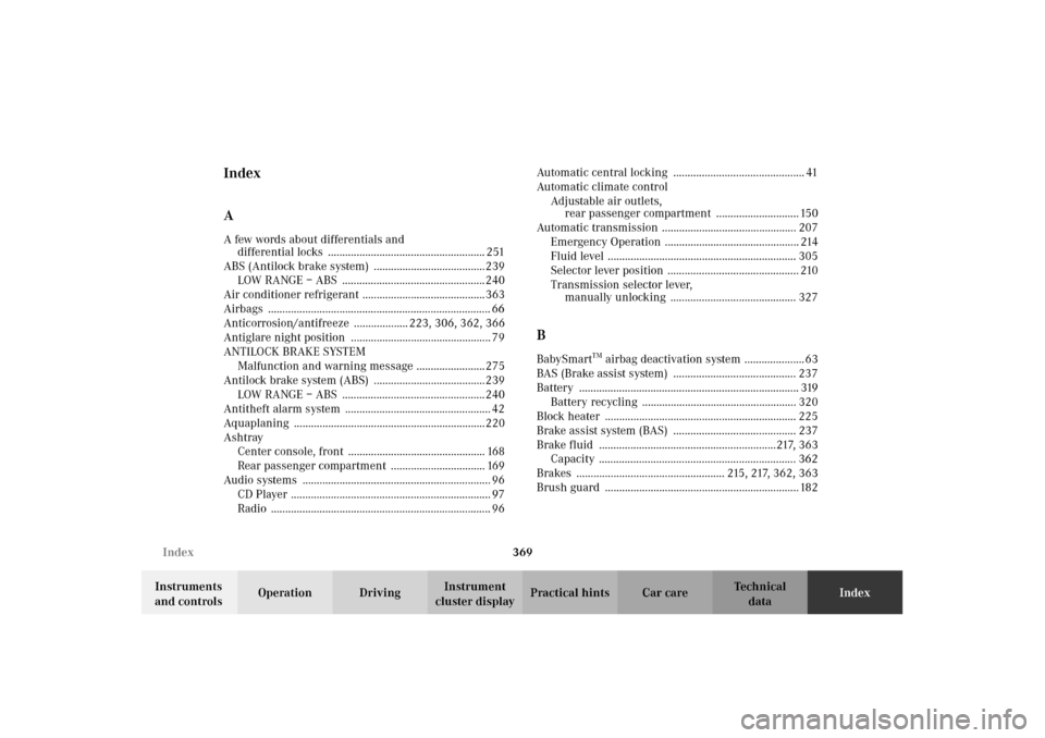
Index
AA few words about differentials and
differential locks ....................................................... 251
ABS (Antilock brake system) .......................................239
LOW RANGE – ABS .................................................. 240
Air conditioner refrigerant ........................................... 363
Airbags .............................................................................. 66
Anticorrosion/antifreeze ................... 223, 306, 362, 366
Antiglare night position ................................................. 79
ANTILOCK BRAKE SYSTEM
Malfunction and warning message ........................ 275
Antilock brake system (ABS) .......................................239
LOW RANGE – ABS .................................................. 240
Antitheft alarm system ................................................... 42
Aquaplaning ...................................................................220
Ashtray
Center console, front ................................................ 168
Rear passenger compartment ................................. 169
Audio systems .................................................................. 96
CD Player ...................................................................... 97
Radio ............................................................................. 96Automatic central locking .............................................. 41
Automatic climate control
Adjustable air outlets,
rear passenger compartment ............................. 150
Automatic transmission ............................................... 207
Emergency Operation ............................................... 214
Fluid level .................................................................. 305
Selector lever position .............................................. 210
Transmission selector lever,
manually unlocking ............................................ 327
BBabySmart
TM airbag deactivation system ..................... 63
BAS (Brake assist system) ........................................... 237
Battery ............................................................................. 319
Battery recycling ...................................................... 320
Block heater ................................................................... 225
Brake assist system (BAS) ........................................... 237
Brake fluid ..............................................................217, 363
Capacity ..................................................................... 362
Brakes .................................................... 215, 217, 362, 363
Brush guard .................................................................... 182
J_G463.book Seite 369 Mittwoch, 19. September 2001 8:06 08