Page 240 of 354
237 Parking system
Te ch n i c a l
data Instruments
and controlsOperationDrivingInstrument
cluster displayPractical hints Car care Index Monitoring reach of sensors
Front bumper:
Rear bumper:The first yellow segment lights up at these distances.
Additional segments light up as the vehicle comes
closer to the obstacle.
Minimum distance between vehicle and obstacle at
which the system stops indicating: Center approx. 40 in (100 cm)
Corner approx. 24 in (60 cm)
Center approx. 48 in (120 cm)
Corner approx. 32 in (80 cm)
P54.65-2299-26
Front corners approx. 6 in (15 cm)
Front center and rear approx. 8 in (20 cm)
P54.65-2300-26
Page 241 of 354

238 Parking system
Te ch n i c a l
data Instruments
and controlsOperationDrivingInstrument
cluster displayPractical hints Car care Index
The obstacle may not be recognized if outside the
shaded sensor field, and no longer be indicated when
approaching it any closer (warning indicators go out).
Parktronic malfunction
All red segments of the warning indicators light up, and
a warning sounds for 3 seconds, if Parktronic does not
function properly.
A dirty sensor could be the reason. (See page 317 for
instructions on cleaning the sensors in the bumpers.)
After cleaning the sensors, turn electronic key in
steering lock to position 2. If the defect continues to be
displayed, have the system checked at your authorized
Mercedes-Benz Center.Parktronic switch
The switch is located on the center console.
1Parktronic switched off
2Parktronic switched on
3Indicator lamp – comes on when Parktronic is
switched off
The parktronic system is switched on again when
turning the electronic key in steering lock position 2.3
Page 244 of 354
241 Check regularly and before a long trip
Te ch n i c a l
data Instruments
and controlsOperationDrivingInstrument
cluster displayPractical hints Car care Index Check regularly and before a long trip
E 320 shown1Windshield washer system
For refilling reservoir see page 276.
2Headlamp cleaning system
Auxiliary tank connected to windshield washer
reservoir. Open filler caps on both reservoirs during
refilling.
3Coolant level
See “Adding coolant”, page 275.
4Engine oil level
See “Checking engine oil level”, page 273.
5Brake fluid
See “Brake fluid”, page 330.
Opening hood, see page 270.
Ve h i c l e l i g h t i n g : Check function and cleanliness. For
replacement of light bulbs, see “Exterior lamps” on
page 297.
Exterior lamp switch, see page 119.
3
2
4
1
5
Page 246 of 354

243 Contents – Instrument cluster display
Te ch n i c a l
data Instruments
and controlsOperation DrivingInstrument
cluster displayPractical hints Car care Index
Instrument cluster displayMalfunction and indicator lamps
in the instrument cluster .........244
On-board diagnostic system .....244
Check engine malfunction
indicator lamp .............................244
Brake warning lamp ..................245
Supplemental restraint system
(SRS) indicator lamp ..................246
Fuel reserve and fuel cap
placement warning ....................246
Electronic stability program
(ESP) — warning lamp ...............247
BAS / ESP malfunction
indicator lamp .............................247ABS malfunction
indicator lamp ............................ 248
Seat belt warning lamp ............. 248
Malfunction and indicator lamp in
the center console .................... 249
AIRBAG OFF indicator lamp .... 249
Malfunction and warning
messages in the
multifunction display .............. 250
DISPLAY DEFECTIVE ................ 251
BATTERY / ALTERNATOR ........ 252
ABS-SYSTEM .............................. 253
BRAKE ASSIST ........................... 253
BRAKE LINING WEAR .............. 254BRAKE FLUID .............................254
PARKING BRAKE .......................255
ENGINE FAN ...............................255
COOLANT (coolant level) ..........256
COOLANT TEMP. ........................257
LIGHTING SYSTEM ....................258
LIGHT SENSOR ...........................259
REMOVE KEY .............................259
STEERING GEAR OIL .................260
ENGINE OIL LEVEL ................... 261
WASHER FLUID .........................262
ELEC. STABIL. PROG.
(Electronic stability program) ..263
TELE AID .....................................263
Page 247 of 354

244 Malfunction and indicator lamps
Te ch n i c a l
data Instruments
and controlsOperation DrivingInstrument
cluster displayPractical hints Car care Index
Malfunction and indicator lamps
in the instrument cluster
General information:
If a bulb in the instrument cluster fails to light up
during the bulb self-check when turning the electronic
key in steering lock to position 2, have it checked and
replaced if necessary.
On-board diagnostic system
Check engine malfunction indicator lamp
Engine malfunction indicator lamp. If the
“CHECK ENGINE” malfunction indicator
lamp comes on when the engine is running,
it indicates a malfunction of the fuel management
system, emission control system, systems which impact
emissions, or the fuel cap is not closed tight (check the
fuel cap). If the “CHECK ENGINE” lamp is illuminated
continuously and the vehicle is driving normally, you
may still drive the vehicle, however, in all cases, we
recommend that you have the system checked at your
authorized Mercedes-Benz Center as soon as possible. If the “CHECK ENGINE” lamp comes on continuously
and / or the vehicle is not driving normally, serious
damage can occur to the emission system. Please
contact your authorized Mercedes-Benz Center
immediately.
The Sequential Multiport Fuel Injection (SFI) control
module monitors emission control components that
either provide input signals to or receive output signals
from the control module. Malfunctions resulting from
interruptions or failure of any of these components are
indicated by the “CHECK ENGINE” malfunction
indicator lamp in the instrument cluster and are
simultaneously stored in the SFI control module.
If the “CHECK ENGINE” malfunction indicator lamp
comes on, have the system checked at your authorized
Mercedes-Benz Center as soon as possible.
With some exceptions, the control module switches off
the “CHECK ENGINE” malfunction indicator lamp if the
condition, causing the lamp to come on, no longer exists
during three consecutive cycles. See also page 246 for
fuel cap placement warning.
CHECK
ENGINE
Page 250 of 354
247 Malfunction and indicator lamps
Te ch n i c a l
data Instruments
and controlsOperation DrivingInstrument
cluster displayPractical hints Car care Index Electronic stability program (ESP) — warning lamp
The yellow ESP warning lamp in the
speedometer dial comes on with the
electronic key in steering lock position 2. It
should go out with engine running.
See page 229 and 230 if the warning lamp lights up or
flashes when the vehicle is moving.BAS / ESP malfunction indicator lamp
The malfunction indicator lamp for the ESP
is combined with that of the BAS.
The yellow BAS / ESP malfunction indicator
lamp in the instrument cluster comes on with the
electronic key in steering lock position 2. It should go
out with the engine running.
If the BAS / ESP malfunction indicator lamp remains
illuminated with the engine running, see page 225 for
notes on brake assist system (BAS) and page 230 for
notes on electronic stability program (ESP).
Page 252 of 354

249 Malfunction and indicator lamps
Te ch n i c a l
data Instruments
and controlsOperation DrivingInstrument
cluster displayPractical hints Car care Index Malfunction and indicator lamp in the center
console
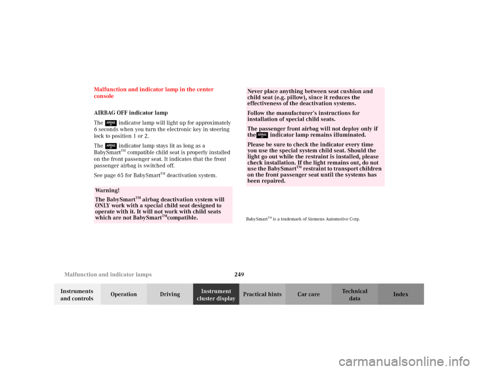
AIRBAG OFF indicator lamp
The 7 indicator lamp will light up for approximately
6 seconds when you turn the electronic key in steering
lock to position 1 or 2.
The 7 indicator lamp stays lit as long as a
BabySmart
TM compatible child seat is properly installed
on the front passenger seat. It indicates that the front
passenger airbag is switched off.
See page 65 for BabySmart
TM deactivation system.
BabySmart
TM is a trademark of Siemens Automotive Corp.
Wa r n i n g !
The BabySmart
TM airbag deactivation system will
ONLY work with a special child seat designed to
operate with it. It will not work with child seats
which are not BabySmart
TMcompatible.
Never place anything between seat cushion and
child seat (e.g. pillow), since it reduces the
effectiveness of the deactivation systems.Follow the manufacturer’s instructions for
installation of special child seats.The passenger front airbag will not deploy only if
the7 indicator lamp remains illuminated.Please be sure to check the indicator every time
you use the special system child seat. Should the
light go out while the restraint is installed, please
check installation. If the light remains out, do not
use the BabySmart
TM restraint to transport children
on the front passenger seat until the systems has
been repaired.
Page 253 of 354

250 Malfunction and warning messages
Te ch n i c a l
data Instruments
and controlsOperation DrivingInstrument
cluster displayPractical hints Car care Index
Malfunction and warning messages in the
multifunction display
Malfunction and warning messages for the following
systems will be displayed immediately in the
multifunction display.
These messages can be cleared from the instrument
cluster by:
•using theJbutton on the instrument cluster, or
•pressing button j, k, è or ÿ on the
multifunction steering wheel.
They are then stored in the malfunction message
memory. See page 108. Notes:
Certain malfunction and warning messages are
accompanied by an audible signal.
Malfunction and warning messages in red are always
accompanied by an audible signal.
Temporary messages such as “SWITCH OFF LIGHTS”
will not be stored in the malfunction message memory.
Wa r n i n g !
All messages contain important information which
should be taken note of and, where malfunction
indicated, addressed as soon as possible at an
authorized Mercedes-Benz Center.Failure to repair condition noted may cause
damage not covered by the Mercedes-Benz Limited
Warranty, or result in property damage or personal
injury.