Page 266 of 354

263 Malfunction and warning messages
Te ch n i c a l
data Instruments
and controlsOperation DrivingInstrument
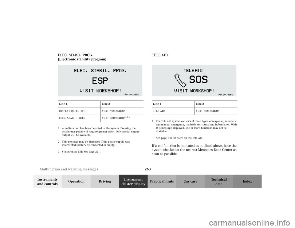
cluster displayPractical hints Car care Index ELEC. STABIL. PROG.
(Electronic stability program)
1 A malfunction has been detected in the system. Pressing the
accelerator pedal will require greater effort. Only partial engine
output will be available.
2 This message may be displayed if the power supply was
interrupted (battery disconnected or empty).
3 Synchronize ESP. See page 231.
TELE AID1 The Tele Aid system consists of three types of response; automatic
and manual emergency, roadside assistance and information. With
this message displayed, one or more functions may not be
avai lable.
See page 188 for notes on the Tele Aid.If a malfunction is indicated as outlined above, have the
system checked at the nearest Mercedes-Benz Center as
soon as possible.
Line 1 Line 2
DISPLAY DEFECTIVE VISIT WORKSHOP!
ELEC. STABIL. PROG. VISIT WORKSHOP!
1, 2, 3
Line 1 Line 2
TELE AID VISIT WORKSHOP!
Page 268 of 354

265 Contents – Practical hints
Te ch n i c a l
data Instruments
and controlsOperation DrivingInstrument
cluster displayPractical hintsCar care Index
Practical hintsFirst aid kit .....................................266
Fuses ................................................267
Electrical outlet ..............................269
Hood .................................................270
Checking engine oil level .............273
Automatic transmission
fluid level ................................... 274
Coolant level ................................... 274
Adding coolant ...........................275
Windshield and headlamp
washer system ........................... 276
Windshield and headlamp
washer fluid mixing ratio ......... 276Spare wheel, vehicle tools,
storage compartment ............... 277
Vehicle jack .................................... 278
Wheels ............................................ 279
Tire replacement ....................... 279
Rotating wheels ......................... 280
Spare wheel .................................... 281
Spare wheel bolts ...................... 281
Changing wheels ........................... 282
Tire inflation pressure ................. 287
Battery ............................................. 289
Jump starting ................................. 291
Towing the vehicle ........................ 294
Transmission selector lever,
manually unlocking ................. 296Exterior lamps ................................297
Headlamp assembly ...................298
Taillamp assemblies .................. 301
Changing batteries
in the electronic main key ......304
Synchronizing
remote control ............................306
Emergency engine shut-down .....306
Emergency operation of
sliding / pop-up roof .................307
Manual release for
fuel filler flap .............................308
Replacing wiper blade insert .......308
Roof rack ..........................................311
Page 269 of 354
266 First aid kit
Te ch n i c a l
data Instruments
and controlsOperation DrivingInstrument
cluster displayPractical hintsCar care Index
First aid kit
1First aid kitThe first aid kit is stored in the cargo area behind the
right hand side trim panel.
To open trim panel:
Release lock and fold down.
Note:
If trim panel was fully removed, make certain to insert
pins (arrows) into retainers in floor when reinstalling.
P86.10-2008-26
11
Page 270 of 354
267 Fuses
Te ch n i c a l
data Instruments
and controlsOperation DrivingInstrument
cluster displayPractical hintsCar care Index Fuses
Before replacing a blown fuse, determine the cause of
the short circuit.
Spare fuses are supplied inside the main fuse box.
Observe amperage and color of fuse.
A special fuse puller is supplied with the vehicle tools.
Always use a new fuse for replacement. Never attempt to
repair or bridge a blown fuse.
A fuse chart can be found inside the corresponding fuse
box cover.
1Main fuses box in engine compartment
To gain access to the main fuse box (1), release clamp
(arrow), lift the fuse box cover up and remove it.
To close the main fuse box, engage right end of cover
and secure with clamp.
P54.15-2068-26
1
Page 271 of 354
268 Fuses
Te ch n i c a l
data Instruments
and controlsOperation DrivingInstrument
cluster displayPractical hintsCar care Index
2Lock for auxiliary fuse box and battery cover
3Fuse box and battery cover4Auxiliary fuse box below right rear bench seat
To gain access, fold seat cushion forward. Rotate lock (2)
counterclockwise and remove cover.
Note:
When reinstalling cover (3) make certain that tabs
(arrows) are inserted.
4
P54.15-2128-26
Page 272 of 354
269 Fuses
Te ch n i c a l
data Instruments
and controlsOperation DrivingInstrument
cluster displayPractical hintsCar care Index 5Auxiliary fuse box to left of exterior lamp switch
To again access, open door, pry off cover and
remove.Electrical outlet
The electrical outlet is located in the rear compartment
on the left side.
To gain access, flip cover up. If locked, first unlock by
inserting for instance a small coin and turning it to the
left.
Note:
The cover is lockable by inserting, for instance a small
coin and turning it to the right.
Maximum capacity: 180 W.
5
P82.00-2029-26
Page 273 of 354

270 Engine compartment
Te ch n i c a l
data Instruments
and controlsOperation DrivingInstrument
cluster displayPractical hintsCar care Index
Hood
Wa r n i n g !
To help prevent personal injury, stay clear of
moving parts when the hood is open and the engine
is running. Be sure the hood is properly closed
before driving. When closing hood, use extreme
caution not to catch hands or fingers.The radiator fan may continue to run for
approximately 30 seconds or even restart after the
engine has been turned off. Stay clear from fan
blades.
If you see flames or smoke coming from the engine
compartment, or if the coolant temperature gauge
indicates that the engine is overheated, do not open
the hood. Move away from vehicle and do not open
the hood until the engine has cooled. If necessary,
call a fire department.The engine is equipped with a transistorized
ignition system. Because of the high voltage it is
dangerous to touch any components (ignition coils,
spark plug sockets, diagnostic socket) of the
ignition system
• with the engine running,
• while starting the engine,
• if ignition is “on” and the engine is turned
manually.
Page 274 of 354
271 Engine compartment
Te ch n i c a l
data Instruments
and controlsOperation DrivingInstrument
cluster displayPractical hintsCar care Index To o p e n :
To unlock the hood, pull release lever (1) under the
driver’s side of the instrument panel. At the same time a
handle will extend out of the radiator grill (it may be
necessary to lift the hood up slightly).
Caution!
To avoid damage to the windshield wiper or hood, open
the hood only with wiper in the parked position.
P68.00-2431-26