2002 MERCEDES-BENZ E WAGON remote control
[x] Cancel search: remote controlPage 185 of 354
182 Garage door opener
Te ch n i c a l
data Instruments
and controlsOperationDrivingInstrument
cluster displayPractical hints Car care Index
Rolling code programming:
To train a garage door opener (or other rolling code
devices) with the rolling code feature, follow these
instructions after completing the “Programming”
portion of this text. (A second person may make the
following training procedures quicker and easier.)
1. Locate training button on the garage door opener
motor head unit. Exact location and color of the
button may vary by garage door opener brand. If
there is difficulty locating the transmitting button,
reference to garage door opener operator’s manual.
2. Press “training” button on the garage door opener
motor head unit (which activated the “training
light”).
Note:
Following step 2, there are 30 seconds to initiate
step 3.3. Firmly press and release the programmed
integrated remote control transmit button. Press
and release same button a second time to complete
the training process. (Some garage door openers
may require you to do this procedure a third time to
complete the training.)
4. Confirm the garage door operation by pressing the
programmed button on the integrated remote
control transmitter.
Canadian programming:
During programming, your hand-held transmitter may
automatically stop transmitting. Continue to press and
hold the integrated remote control transmitter button
(note steps 2 through 4 in the “Programming” portion)
while you press and re-press (“cycle”) your hand-held
transmitter every two seconds until the frequency
signal has been learned. The indicator lamp will flash
slowly and then rapidly after several seconds upon
successful training.
Page 186 of 354
183 Garage door opener
Te ch n i c a l
data Instruments
and controlsOperationDrivingInstrument
cluster displayPractical hints Car care Index Operation of remote control:
1. Turn electronic key in steering lock to position 1
or 2.
2. Select and press the appropriate button to activate
the remote controlled device. The integrated remote
control transmitter continues to send the signal as
long as the button is pressed – up to 20 seconds.Erasing the remote control memory:
1. Turn electronic key in steering lock to position 1
or 2.
2. Simultaneously holding down the left and right side
buttons for approximately 20 seconds, or until the
control lamp blinks rapidly, will erase the codes of
all three channels.
Page 191 of 354

188 Tele Aid
Te ch n i c a l
data Instruments
and controlsOperationDrivingInstrument
cluster displayPractical hints Car care Index
Tele Aid (optional for Canada)
Important!
The initial activation of the Tele Aid system may only be
performed by completing the subscriber agreement and
placing an acquaintance call using the “SOS” button.
Failure to complete either of these steps will result in a
system that is not activated. If the system is not
activated the indicator lamp in the “SOS” button stays
on after turning electronic key in steering lock to
position 2 and the message “TELE AID – NOT
ACTIVATED” will be shown in the multifunction display
for approx. 10 seconds.
If you have any questions regarding activation, please
call the Response Center at 1-800-756-9018 (in the USA)
or 1-888-923-8367 (in Canada).
(Te l ematic Alarm Identification on Demand)
The Tele Aid system consists of three types of response;
automatic and manual emergency, roadside assistance
and information.
The Tele Aid system is operational providing that the
vehicle’s battery is charged, properly connected, not
damaged and cellular and GPS coverage is available.The speaker volume of a Tele Aid call can be adjusted
when using the volume control on the multifunction
steering wheel, for raising press buttonæand for
lowering press buttonç.
To activate, press the “SOS” button, the Roadside
Assistance button• or the Information button¡,
depending on the type of response required.
Shortly after the completion of your Acquaintance Call,
you will receive a user ID and password via first call
mail. By visiting www.mbusa.com and selecting
“Tele Aid” (USA only), you will have access to account
information, remote door unlock, Info Services
* profile
and more.
* Optional – available only with COMAND System self-check
Initially, after turning the electronic key in steering lock
to position 2, malfunctions are detected and indicated
(the indicator lamps in the “SOS” button, the Roadside
Assistance button• and the Information
button¡ stay on longer than 10 seconds or do not
come on). The message “TELE AID – VISIT
WORKSHOP” appears for approx. 10 seconds in the
multifunction display.
Page 195 of 354
192 Tele Aid
Te ch n i c a l
data Instruments
and controlsOperationDrivingInstrument
cluster displayPractical hints Car care Index
Roadside Assistance button •
Located below the center armrest cover is the Roadside
Assistance button•. Pressing and holding the
button (for longer than 2 seconds) will initiate a call to a
Mercedes-Benz Roadside Assistance dispatcher. The
button will flash while the call is in progress. The
message “ROADSIDE ASSISTANCE – CONNECTING
CALL” will appear in the multifunction display. When
the connection is established, the message “ROADSIDE
ASSISTANCE – CALL CONNECTED” appears in the
multifunction display. The Tele Aid system will transmit
data generating the vehicle identification number,
model, color and location (subject to availability of
cellular and GPS signals).
A voice connection between the Roadside Assistance
dispatcher and the occupants of the vehicle will be
established. When a voice connection is established the
audio system mutes and the message “TELE AID –
ROADSIDE ASSISTANCE CALL ACTIVE” appears in the
multifunction display. The nature of the need for
assistance can then be described. The Mercedes-Benz
Roadside assistance dispatcher will either dispatch a
qualified Mercedes-Benz technician or arrange to tow
your vehicle to the nearest Mercedes-Benz Center. For services such as labor and/or towing charges may
apply. Refer to the Roadside Assistance manual for more
information.
These programs are only available in the USA:
•Sign and Drive services: Services such as jump start,
a few gallons of fuel or the replacement of a flat tire
with the vehicle spare tire are obtainable,
•Remote Vehicle Diagnostics: This function permits
the Mercedes-Benz Roadside Assistance dispatcher
to download malfunction codes and actual vehicle
data.
Notes:
The indicator lamp in the Roadside Assistance
button• remains illuminated in red for approx.
10 seconds during the system self-check after turning
electronic key in steering lock to position 2 (together
with the “SOS” button and the Information
button¡).
See system self-check on page 188 when the indicator
lamp does not light up in red or stays on longer than
approximately 10 seconds.
Page 199 of 354
196 Tele Aid
Te ch n i c a l
data Instruments
and controlsOperationDrivingInstrument
cluster displayPractical hints Car care Index
Remote door unlock
In the case you have your vehicle locked unintentionally
(e.g. key inside vehicle), and no other key is available,
contact the Mercedes-Benz Response Center at
1-800-756-9018 (in the USA) or 1-888-923-8367 (in
Canada). You will be asked to provide your password
which you provided when you completed the subscriber
agreement.
Then return to your vehicle and pull tailgate recessed
handle for minimum of 20 seconds until the “SOS”
button is flashing. The message “EMERGENCY CALL -
CALL CONNECTED” appears in the multifunction
display.
As an alternative, you may unlock the vehicle via
Internet using the ID and password sent to you shortly
after the completion of your Acquaintance Call.
The Response Center will then unlock your vehicle with
the remote door unlocking feature.Notes:
The remote door unlock feature is available if the
relevant cellular phone network is available.
The SOS button will flash and the message
“EMERGENCY CALL – CALL CONNECTED” will appear
in the multifunction display to indicate receipt of the
door unlock command.
Once the vehicle is unlocked, a Response Center
specialist will attempt to establish voice contact with the
vehicle occupants.
If the tailgate recessed handle was pulled for more than
20 seconds before door unlock authorization was
received by the Response Center, you must wait
15 minutes before pulling the tailgate recessed handle
again.
Page 268 of 354
265 Contents – Practical hints
Te ch n i c a l
data Instruments
and controlsOperation DrivingInstrument
cluster displayPractical hintsCar care Index
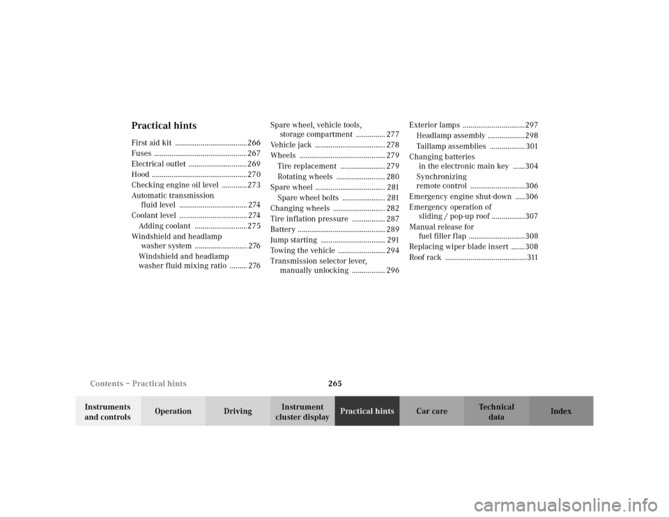
Practical hintsFirst aid kit .....................................266
Fuses ................................................267
Electrical outlet ..............................269
Hood .................................................270
Checking engine oil level .............273
Automatic transmission
fluid level ................................... 274
Coolant level ................................... 274
Adding coolant ...........................275
Windshield and headlamp
washer system ........................... 276
Windshield and headlamp
washer fluid mixing ratio ......... 276Spare wheel, vehicle tools,
storage compartment ............... 277
Vehicle jack .................................... 278
Wheels ............................................ 279
Tire replacement ....................... 279
Rotating wheels ......................... 280
Spare wheel .................................... 281
Spare wheel bolts ...................... 281
Changing wheels ........................... 282
Tire inflation pressure ................. 287
Battery ............................................. 289
Jump starting ................................. 291
Towing the vehicle ........................ 294
Transmission selector lever,
manually unlocking ................. 296Exterior lamps ................................297
Headlamp assembly ...................298
Taillamp assemblies .................. 301
Changing batteries
in the electronic main key ......304
Synchronizing
remote control ............................306
Emergency engine shut-down .....306
Emergency operation of
sliding / pop-up roof .................307
Manual release for
fuel filler flap .............................308
Replacing wiper blade insert .......308
Roof rack ..........................................311
Page 309 of 354
306 Electronic key
Te ch n i c a l
data Instruments
and controlsOperation DrivingInstrument
cluster displayPractical hintsCar care Index
Important!
Batteries contain materials that can harm the
environment if disposed of improperly. Recycling of
batteries is the preferred method of disposal. For
disposal, please follow manufacturer’s recommendation
on battery package.
Replacement Battery:
Lithium, type CR 2025 or equivalent.
Synchronizing remote control
The remote control may have to be resynchronized, if
the vehicle cannot be locked or unlocked.
To synchronize insert electronic key in starter switch.
The remote control should once again be operational.Emergency engine shut-down
If the engine can no longer be stopped using the
electronic key, the engine can be turned off by removing
two fuses.
For easy removal of fuses use the fuse extractor
(supplied with vehicle tool kit) to pull out the fuses
marked on the fuse chart as “ENGINE EMERGENCY
OFF”.
The fuse chart is also located in the vehicle tool kit,
seepage277.
For fuses see page 267.
Page 341 of 354

338 Index
Te ch n i c a l
data Instruments
and controlsOperation DrivingInstrument
cluster displayPractical hints Car careIndex
Center console .................................................................. 20
Central locking switch .................................................... 34
Central locking system ................................................... 27
Automatic central locking ......................................... 35
Choosing global or selective mode ........................... 30
Electronic key .............................................................. 25
Locking and unlocking .............................................. 29
Mechanical keys .......................................................... 31
Remote control ............................................................ 25
Summer opening/convenience feature ................... 30
CHECK ENGINE
malfunction indicator lamp ..................................... 244
Check regularly and before a long trip ...................... 241
Checking engine oil level
Via engine oil level indicator ...................................117
Via oil dipstick ...........................................................273
Child restraint ..................................................... 57, 65, 77
Child seat
Infant and child restraint systems ........................... 77
Cleaning and care of the vehicle ................................. 314
Clock, setting ...................................................................110
Coin holder in glove box lid ......................................... 163
COMAND, radio, telephone and two-way radio ........ 186
Combination switch ...................................................... 122
Consumer information .................................................. 334
Control and operation of radio transmitters ............. 186COOLANT (coolant level) -
malfunction and warning messages ..................... 256
Coolant level ................................................................... 274
Adding coolant .......................................................... 275
Checking ..................................................................... 274
COOLANT TEMP. -
malfunction and warning messages ..................... 257
Coolant temperature gauge ............................................90
Coolants .......................................................................... 332
Anticorrosion/antifreeze quantity ........................ 333
Cruise control ................................................................ 222
Cup holder
In center console ....................................................... 165
In glove box lid .......................................................... 163
In rear bench armrest ............................................... 162
DDaytime running lamps ................................................120
Deep water
Driving instructions .................................................221
DISPLAY DEFECTIVE (engine control unit) -
malfunction and warning messages ......................251
DISPLAY DEFECTIVE (several systems) -
malfunction and warning messages ......................251
Display illumination ........................................................89