2002 MERCEDES-BENZ CLK55AMG CABRIOLET brake light
[x] Cancel search: brake lightPage 209 of 346

206 Driving instructions
Technical
data Instruments
and controlsOperationDrivingInstrument
cluster displayPractical hints Car care Index
Power assistance
BrakesExcessive use of salt and other snow melting chemicals
spread on roads during the winter months may cause a
build up of moisture or residue to form on the braking
components. This build up or residue could cause light
corrosion of the braking components if the vehicle is
parked with the brakes cold. Apply steady and even
braking pressure when stopping the vehicle to warm up
and dry the brake components.
Important!
Please pay attention to the function of the brake assist
system (BAS), see page 216.
The condition of the parking brake system is checked
each time the vehicle is in the shop for the required
maintenance service at an authorized Mercedes-Benz
Center.
If the parking brake is released and the brake warning
lamp in the instrument cluster stays on, the brake fluid
level in the reservoir is too low.
Brake pad wear or a leak in the system may be the
reason for low brake fluid in the reservoir.
Have the brake system inspected at an authorized
Mercedes-Benz Center immediately.
Wa r n i n g !
When the engine is not running, the brake and
steering systems are without power assistance.
Under these circumstances, a much greater effort is
necessary to stop or steer the vehicle.Wa r n i n g !
After driving in heavy rain for some time without
applying the brakes or through water deep enough
to wet brake components or salty road conditions,
the first braking action may be somewhat reduced
and increased pedal pressure may be necessary to
obtain expected braking effect. Be sure to maintain
a safe distance from vehicles in front.Resting your foot on the brake pedal will cause
excessive and premature wear of the brake pads.It can also result in the brakes overheating thereby
significantly reducing their effectiveness. It may
not be possible to stop the vehicle in sufficient time
to avoid an accident.
J_A208.book Seite 206 Donnerstag, 31. Mai 2001 9:35 09
Page 221 of 346

218 Driving systems
Technical
data Instruments
and controlsOperationDrivingInstrument
cluster displayPractical hints Car care Index
Antilock brake system (ABS)
Important!
The ABS improves steering control of the vehicle during
hard braking maneuvers.
The ABS prevents the wheels from locking up above a
vehicle speed of approximately 5 mph (8 km/h)
independent of road surface conditions.At the instant one of the wheels is about to lock up, a
slight pulsation can be felt in the brake pedal,
indicating that the ABS is in the regulating mode. Keep
firm and steady pressure on the brake pedal while
experiencing the pulsation.
Continuous steady brake pedal pressure results in
applying the advantages of the ABS, namely braking
power and ability to steer the vehicle.
In the case of an emergency brake maneuver keep
continuous full pressure on the brake pedal. In this
manner only can the ABS be most effective.
On slippery road surfaces, the ABS will respond even
with light brake pedal pressure because of the
increased likelihood of locking wheels. The pulsating
brake pedal can be an indication of hazardous road
conditions and functions as a reminder to take extra
care while driving.
Wa r n i n g !
Do not pump the brake pedal, rather use firm,
steady brake pedal pressure. Pumping the brake
pedal defeats the purpose for ABS and significantly
reduces braking effectiveness.
J_A208.book Seite 218 Donnerstag, 31. Mai 2001 9:35 09
Page 229 of 346

226 Check regularly and before a long trip
Technical
data Instruments
and controlsOperationDrivingInstrument
cluster displayPractical hints Car care Index
Check regularly and before a long trip 1Engine oil level
See “Engine oil level, checking” on page 112 and
page 256.
2Coolant level
See “Coolant level” on page 257.
3Brake fluid
See “Brake fluid” on page 320.
4Windshield washer system
Headlamp cleaning system
For refilling reservoir see page 259.
Opening hood, see page 254.
Ve h i c l e l i g h t i n g : Check function and cleanliness. For
replacement of light bulbs, see “Exterior lamps” on
page 280.
Exterior lamp switch, see page 114.
J_A208.book Seite 226 Donnerstag, 31. Mai 2001 9:35 09
Page 230 of 346

227 Contents – Instrument cluster display
Technical
data Instruments
and controlsOperation DrivingInstrument
cluster displayPractical hints Car care Index
Instrument cluster displayMalfunction and
indicator lamps in the
instrument cluster ....................228
On-board diagnostic system
Check engine malfunction
indicator lamp .............................228
Brake warning lamp ..................229
Supplemental restraint
system (SRS) indicator lamp ....230
Fuel reserve and fuel cap
placement warning ....................230
Electronic stability program
(ESP) — warning lamp ............... 231
BAS/ESP malfunction
indicator lamp ............................. 231
ABS malfunction
indicator lamp ............................. 231
Telescoping steering column –
indicator lamp .............................232
Seat belt warning lamp .............232Malfunction and
indicator lamps in the
center console ........................... 232
AIRBAG OFF indicator lamp .... 232
Roll bar warning lamp .............. 233
Malfunction and
warning messages in the
multifunction display .............. 234
DISPLAY DEFECTIVE
(engine control unit) ................. 235
DISPLAY DEFECTIVE
(several systems) ....................... 235
BATTERY/ALTERNATOR .......... 236
ABS-SYSTEM .............................. 237
BRAKE ASSIST ........................... 237
BRAKE LINING WEAR .............. 238
BRAKE FLUID ............................ 238
PARKING BRAKE ....................... 239
ENGINE FAN ............................... 239
COOLANT (coolant level) ......... 240
COOLANT TEMP.
(coolant temperature) ............... 241LIGHTING SYSTEM ....................242
LIGHT SENSOR ...........................243
STEER. WHEEL ADJUST. ...........243
ENGINE OIL LEVEL ...................244
ELEC. STABIL. PROG.
(Electronic stability
program) ......................................245
REMOVE KEY .............................245
WASHER FLUID .........................246
TELE AID .....................................247
J_A208.book Seite 227 Donnerstag, 31. Mai 2001 9:35 09
Page 231 of 346

228 Malfunction and indicator lamps
Technical
data Instruments
and controlsOperation DrivingInstrument
cluster displayPractical hints Car care Index
Malfunction and indicator lamps
in the instrument cluster
General information:
If a bulb in the instrument cluster fails to light up
during the bulb self-check when turning the electronic
key in steering lock to position 2, have it checked and
replaced if necessary.
On-board diagnostic system
Check engine malfunction indicator lamp
Engine malfunction indicator lamp. If the
“CHECK ENGINE” malfunction indicator
lamp comes on when the engine is running,
it indicates a malfunction of the fuel management
system, emission control system, systems which impact
emissions, or the fuel cap is not closed tight (check the
fuel cap). If the “CHECK ENGINE” lamp is illuminated
continuously and the vehicle is driving normally, you
may still drive the vehicle, however, in all cases, we
recommend that you have the system checked at your
authorized Mercedes-Benz Center as soon as possible.
If the “CHECK ENGINE” lamp comes on continuously
and / or the vehicle is not driving normally (e.g.
malfunction of the fuel management system or running out of fuel), serious damage can occur to the emission
system. Please contact your authorized Mercedes-Benz
Center immediately.
The Sequential Multiport Fuel Injection (SFI) control
module monitors emission control components that
either provide input signals to or receive output signals
from the control module. Malfunctions resulting from
interruptions or failure of any of these components are
indicated by the “CHECK ENGINE” malfunction
indicator lamp in the instrument cluster and are
simultaneously stored in the SFI control module.
If the “CHECK ENGINE” malfunction indicator lamp
comes on, have the system checked at your authorized
Mercedes-Benz Center as soon as possible.
With some exceptions, the control module switches off
the “CHECK ENGINE” malfunction indicator lamp if the
condition, causing the lamp to come on, no longer exists
during three consecutive cycles. See also page 230 for
fuel cap placement warning.
An on-board diagnostic connector is located in the
passenger compartment near to the parking brake
pedal, allowing the accurate identification of system
malfunctions through the readout of diagnostic trouble
codes.
CHECK
ENGINE
J_A208.book Seite 228 Donnerstag, 31. Mai 2001 9:35 09
Page 234 of 346

231 Malfunction and indicator lamps
Technical
data Instruments
and controlsOperation DrivingInstrument
cluster displayPractical hints Car care Index Electronic stability program (ESP) — warning lamp
The yellow ESP warning lamp in the
speedometer dial comes on with the
electronic key in steering lock position 2.
It should go out with engine running.
See page 220 if the warning lamp lights up or flashes
when the vehicle is moving.
BAS / ESP malfunction indicator lamp
The malfunction indicator lamp for the ESP
is combined with that of the BAS.
The yellow BAS/ESP malfunction indicator
lamp in the instrument cluster comes on with the
electronic key in steering lock position 2. It should go
out with the engine running.
If the BAS/ESP malfunction indicator lamp remains
illuminated with the engine running, see page 216 for
notes on the brake assist (BAS) and page 220 for notes
on the electronic stability program (ESP).ABS malfunction indicator lamp
The ABS malfunction indicator lamp in the
instrument cluster comes on with the
electronic key in steering lock position 2 and
should go out with the engine running.
When the ABS malfunction indicator lamp and the
malfunction message in the instrument cluster remains
illuminated while the engine is running, it indicates
that the ABS has detected a malfunction and has
switched off. In this case, the brake system functions in
the usual manner, but without antilock assistance.
With the ABS malfunctioning, the BAS and ESP are also
switched off. Both malfunction indicator lamps and the
ABS malfunction message in the multifunction display
come on with the engine running.
If the charging voltage falls below 10 volts, the
malfunction indicator lamp comes on and the ABS is
switched off. When the voltage is above this value again,
the malfunction indicator lamp should go out and the
ABS is operational.
Have the system checked at your authorized
Mercedes-Benz Center as soon as possible.
See page 218 for notes on the antilock brake system
(ABS).
BAS
ESP
ABS
J_A208.book Seite 231 Donnerstag, 31. Mai 2001 9:35 09
Page 245 of 346

242 Malfunction and warning messages
Technical
data Instruments
and controlsOperation DrivingInstrument
cluster displayPractical hints Car care Index
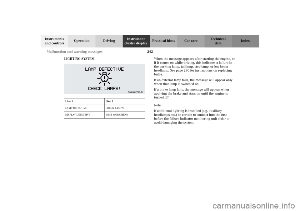
LIGHTING SYSTEMWhen the message appears after starting the engine, or
if it comes on while driving, this indicates a failure in
the parking lamp, taillamp, stop lamp, or low beam
headlamp. See page 280 for instructions on replacing
bulbs.
If an exterior lamp fails, the message will appear only
when that lamp is switched on.
If a brake lamp fails, the message will appear when
applying the brake and stays on until the engine is
turned off.
Note:
If additional lighting is installed (e.g. auxiliary
headlamps etc.) be certain to connect into the fuse
before the failure indicator monitoring unit order to
avoid damaging the system.
Line 1 Line 2
LAMP DEFECTIVE CHECK LAMPS!
DISPLAY DEFECTIVE VISIT WORKSHOP!
J_A208.book Seite 242 Donnerstag, 31. Mai 2001 9:35 09
Page 278 of 346

275 Jump starting
Technical
data Instruments
and controlsOperation DrivingInstrument
cluster displayPractical hintsCar care Index Proceed as follows:
1. Position the vehicle with the charged battery so that
the jumper cables will reach, but never let the
vehicles touch. Make sure the jumper cables do not
have loose or missing insulation.
2. On both vehicles:
•Turn off engine and all lights and accessories,
except hazard warning flashers or work lights.
•Apply parking brake and shift selector lever to
position “P”.
Important!
3. Clamp one end of the first jumper cable to the
positive (+) under hood terminal of the discharged
battery and the other end to the positive (+) terminal
of the charged battery. Make sure the cable clamps
do not touch any other metal parts.
4. Clamp one end of the second jumper cable to the
grounded negative (–) terminal of the charged
battery and the final connection to the negative (–)
terminal (2) of the discharged battery.Important!
5. Start engine of the vehicle with the charged battery
and run at high idle. Make sure the cables are not
on or near pulleys, fans, or other parts that move
when the engine is started. Allow the discharged
battery to charge for a few minutes. Start engine of
the disabled vehicle in the usual manner.
6. After the engine has started, remove jumper cables
by exactly reversing the above installation
sequence, starting with the last connection made
first. When removing each clamp, make sure that it
does not touch any other metal while the other end
is still attached.
Notes:
If engine does not run after several unsuccessful
starting attempts, have it checked at the nearest
authorized Mercedes-Benz Center.
Excessive unburned fuel may damage the catalytic
converter.
J_A208.book Seite 275 Donnerstag, 31. Mai 2001 9:35 09