Page 232 of 330

229 Malfunction and indicator lamps
Technical
data Instruments
and controlsOperation DrivingInstrument
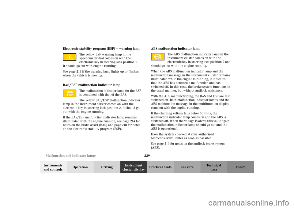
cluster displayPractical hints Car care Index Electronic stability program (ESP) — warning lamp
The yellow ESP warning lamp in the
speedometer dial comes on with the
electronic key in steering lock position 2.
It should go out with engine running.
See page 218 if the warning lamp lights up or flashes
when the vehicle is moving.
BAS / ESP malfunction indicator lamp
The malfunction indicator lamp for the ESP
is combined with that of the BAS.
The yellow BAS/ESP malfunction indicator
lamp in the instrument cluster comes on with the
electronic key in steering lock position 2. It should go
out with the engine running.
If the BAS/ESP malfunction indicator lamp remains
illuminated with the engine running, see page 214 for
notes on the brake assist (BAS) and page 218 for notes
on the electronic stability program (ESP).ABS malfunction indicator lamp
The ABS malfunction indicator lamp in the
instrument cluster comes on with the
electronic key in steering lock position 2 and
should go out with the engine running.
When the ABS malfunction indicator lamp and the
malfunction message in the instrument cluster remains
illuminated while the engine is running, it indicates
that the ABS has detected a malfunction and has
switched off. In this case, the brake system functions in
the usual manner, but without antilock assistance.
With the ABS malfunctioning, the BAS and ESP are also
switched off. Both malfunction indicator lamps and the
ABS malfunction message in the multifunction display
come on with the engine running.
If the charging voltage falls below 10 volts, the
malfunction indicator lamp comes on and the ABS is
switched off. When the voltage is above this value again,
the malfunction indicator lamp should go out and the
ABS is operational.
Have the system checked at your authorized
Mercedes-Benz Center as soon as possible.
See page 216 for notes on the antilock brake system
(ABS).
BAS
ESP
ABS
J_C208_II.book Seite 229 Donnerstag, 31. Mai 2001 10:13 10
Page 234 of 330

231 Malfunction and indicator lamps
Technical
data Instruments
and controlsOperation DrivingInstrument
cluster displayPractical hints Car care Index Malfunction and indicator lamps in the center
console
AIRBAG OFF indicator lamp
The 7 indicator lamp will light up for approx.
6 seconds when you turn the electronic key in steering
lock to position 1 or 2.
The 7 indicator lamp stays lit as long as a
BabySmart
TM compatible child seat is properly installed
on the front passenger seat. It indicates that the front
passenger airbag is switched off.
See page 65 for BabySmart
TM deactivation system.
BabySmart
TM is a trademark of Siemens Automotive Corp.
Wa r n i n g !
The BabySmart
TM airbag deactivation system will
ONLY work with a special child seat designed to
operate with it. It will not work with child seats
which are not BabySmart
TM compatible.
Never place anything between seat cushion and
child seat (e.g. pillow), since it reduces the
effectiveness of the deactivation system.Follow the manufacturer’s instructions for
installation of special child seats.The passenger side front airbag will not deploy
only if the 7 indicator lamp remains
illuminated.Please be sure to check the indicator every time
you use the special system child seat.Should the light go out while the restraint is
installed, please check installation. If the light
remains out, do not use the BabySmart
TM restraint
to transport children on the front passenger seat
until the system has been repaired.
J_C208_II.book Seite 231 Donnerstag, 31. Mai 2001 10:13 10
Page 235 of 330

232 Malfunction and warning messages
Technical
data Instruments
and controlsOperation DrivingInstrument
cluster displayPractical hints Car care Index
Malfunction and warning messages in the
multifunction display
Malfunction and warning messages for the following
systems will be displayed immediately in the
multifunction display.
These messages can be cleared from the instrument
cluster by:
•using the J button on the instrument cluster, or
•pressing buttonj, k, è or ÿ on the
multifunction steering wheel.
They are then stored in the malfunction message
memory. See page 106.Notes:
Certain malfunction and warning messages are
accompanied by an audible signal.
Malfunction and warning messages in red are always
accompanied by an audible signal.
Temporary messages such as “SWITCH OFF LIGHTS”
will not be stored in the malfunction message memory.
Wa r n i n g !
All messages contain important information which
should be taken note of and, where malfunction
indicated, addressed as soon as possible at an
authorized Mercedes-Benz Center.Failure to repair condition noted may cause
damage not covered by the Mercedes-Benz Limited
Warranty, or result in property damage or personal
injury.
J_C208_II.book Seite 232 Donnerstag, 31. Mai 2001 10:13 10
Page 243 of 330
240 Malfunction and warning messages
Technical
data Instruments
and controlsOperation DrivingInstrument
cluster displayPractical hints Car care Index
LIGHTING SYSTEMWhen the message appears after starting the engine, or
if it comes on while driving, this indicates a failure in
the parking lamp, taillamp, stop lamp, or low beam
headlamp. See page 275 for instructions on replacing
bulbs.
If an exterior lamp fails, the message will appear only
when that lamp is switched on.
If a brake lamp fails, the message will appear when
applying the brake and stays on until the engine is
turned off.
Note:
If additional lighting is installed (e.g. auxiliary
headlamps etc.) be certain to connect into the fuse
before the failure indicator monitoring unit order to
avoid damaging the system.
Line 1 Line 2
LAMP DEFECTIVE CHECK LAMPS!
DISPLAY DEFECTIVE VISIT WORKSHOP!
J_C208_II.book Seite 240 Donnerstag, 31. Mai 2001 10:13 10
Page 244 of 330
241 Malfunction and warning messages
Technical
data Instruments
and controlsOperation DrivingInstrument
cluster displayPractical hints Car care Index LIGHT SENSOR
With the electronic key removed and the driver’s door
open, a warning sounds and the message “SWITCH OFF
LIGHTS!” appears in the multifunction indicator if the
vehicle’s exterior lamps (except standing lamps) are not
switched off.STEER. WHEEL ADJUST.
For locking the adjustable telescoping steering column,
see page 79.
Line 1 Line 2
STEER. WHEEL ADJUST.
J_C208_II.book Seite 241 Donnerstag, 31. Mai 2001 10:13 10
Page 255 of 330
252 Engine compartment
Technical
data Instruments
and controlsOperation DrivingInstrument
cluster displayPractical hintsCar care Index
To o pen :
To unlock the hood, pull release lever (1) under the
driver’s side of the instrument panel. At the same time a
handle will extend out of the radiator grill (it may be
necessary to lift the hood up slightly).
Caution!
To avoid damage to the windshield wiper or hood, open
the hood only with wiper in the parked position.Pull handle (2) to its stop out of radiator grill and open
hood (do not pull up on handle).
To c l o s e :
Lower hood and let it drop into lock from a height of
approx. 1 f t. (30 cm), assisting with hands placed f lat on
edges of hood (3).
To avoid hood damage, please make sure that hood is
fully closed. If not, repeat closing procedure. Do not
push down on hood to attempt to fully close it.
P88.40-2025-26
1
3
2
3
J_C208_II.book Seite 252 Donnerstag, 31. Mai 2001 10:13 10
Page 268 of 330
265 Tires, Wheels
Technical
data Instruments
and controlsOperation DrivingInstrument
cluster displayPractical hintsCar care Index 10. Clean contact surfaces of wheel and wheel hub.
Install spare wheel on wheel hub. Insert wheel bolts
and tighten them slightly.
To avoid paint damage, place wheel flat against hub
and hold it there while installing first wheel bolt.
Unscrew the alignment bolt (1) to install the last
wheel bolt.11. Lower vehicle. Remove jack and insert jack tube
cover.
12. Using the wrench, tighten the five bolts evenly,
following the sequence illustrated, until all bolts are
tight.
Observe a tightening torque of 80 ft.lb. (110 Nm).
Before storing the jack, the jack arm must be
lowered almost to the base of the jack. For proper
storage of vehicle jack see page 258.
13. Ensure proper tire pressure.
1
1
J_C208_II.book Seite 265 Donnerstag, 31. Mai 2001 10:13 10
Page 270 of 330

267 Tires, Wheels
Technical
data Instruments
and controlsOperation DrivingInstrument
cluster displayPractical hintsCar care Index Tire inflation pressure
A table (see fuel filler flap) lists the tire inflation
pressures specified for Mercedes-Benz recommended
tires as well as for the varying operating conditions.
Important!
Tire pressure changes by approx. 1.5 psi (0.1 bar) per
18
°F (10
°C) of air temperature change. Keep this in
mind when checking tire pressure inside a garage –
especially in the winter.
Example:
If garage temperature = approx. +68
°F (+20
°C) and
ambient temperature = approx. +32
°F (0
°C) then the
adjusted air pressure = specified air pressure +3 psi
(+0.2 bar).Tire pressures listed for light loads are minimum values
offering high driving comfort. Increased inflation
pressures for heavy loads produce favorable handling
characteristics with lighter loads and are perfectly
permissible. The ride of the vehicle, however, will
become somewhat harder.
Tire temperature and pressure increase with the vehicle
speed. Tire pressure should therefore only be checked
and corrected on cold tires. Correct tire pressure in
warm tires only if pressure has dropped below the
pressure listed in the table and the respective operating
conditions are taken into consideration.
An underinflated tire due to a slow leak (e.g. due to a
nail in the tire) may cause damage such as tread
separation, bulging etc.. Regular tire pressure checks
(including the spare tire) at intervals of no more than
14 days are therefore essential.
J_C208_II.book Seite 267 Donnerstag, 31. Mai 2001 10:13 10