2002 MERCEDES-BENZ CLK-CLASS tow
[x] Cancel search: towPage 170 of 341

167 Wind screen
Te ch n i c a l
data Instruments
and controlsOperationDrivingInstrument
cluster displayPractical hints Car care Index Important!
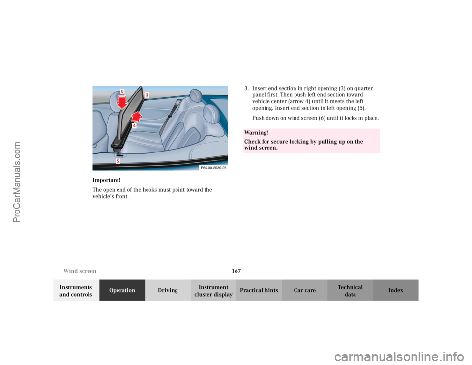
The open end of the hooks must point toward the
vehicle’s front. 3. Insert end section in right opening (3) on quarter
panel first. Then push left end section toward
vehicle center (arrow 4) until it meets the left
opening. Insert end section in left opening (5).
Push down on wind screen (6) until it locks in place.
P65.00-2039-26
3
4
56
Wa r n i n g !
Check for secure locking by pulling up on the
wind screen.
ProCarManuals.com
Page 173 of 341

170 Wind screen
Te ch n i c a l
data Instruments
and controlsOperationDrivingInstrument
cluster displayPractical hints Car care Index
Roller Blind (horizontal) To o p e n b l i n d :
1. Pull out blind on tab (arrow 1) towards vehicles rear.
Insert guide rod of blind in right rear seat belt outlet
(arrow 2).
2. Insert other end of rod in left rear seat belt outlet as
shown with arrow (3).
Important!
Do not place anything on the roller blind.
To retract blind:
•Hold blind at tab, disengage and guide retraction.
3
1
2
P65.00-2049-26
ProCarManuals.com
Page 174 of 341

171 Wind screen
Te ch n i c a l
data Instruments
and controlsOperationDrivingInstrument
cluster displayPractical hints Car care Index Roller Blind (vertical) To o p e n b l i n d :
1. Fold driver and front passenger seat backrests
forward.
2. Pull out on tab, located below rear bench, towards
vehicle’s front, then pull up and engage blind at
wind screen.
To retract blind:
1. Fold driver and front passenger seat backrests
forward.
2. Hold blind at tab, disengage and guide its retraction.
P65.00-2018-26
ProCarManuals.com
Page 182 of 341

179 Tele Aid
Te ch n i c a l
data Instruments
and controlsOperationDrivingInstrument
cluster displayPractical hints Car care Index System self-check
Initially, after turning the electronic key in starter
switch to position 2, malfunctions are detected and
indicated (the indicator lamps in the SOS button, the
Roadside Assistance button• and the Information
button¡ stay on longer than 10 seconds or do not
come on). The message “TELE AID – VISIT
WORKSHOP” appears for approx. 10 seconds in the
multifunction display. Important!
Always make sure that the indicator lamps in the is not
displayed in the multifunction display after the system
self check.
If a malfunction is indicated as outlined above, have the
system checked at the nearest Mercedes-Benz Center as
soon as possible.
Emergency calls
An emergency call is initiated automatically:
•following an accident in which the Emergency
Tensioning Devices (ETDs) or airbags deploy,
•if the antitheft alarm or the tow away alarm stays on
for more than 20 seconds, see pages 39 and 40.
An emergency call can also be initiated manually by
opening the cover next to the inside rear view mirror
labeled SOS, then briefly pressing the button located
under the cover. See below for instructions on initiating
an emergency call manually.
Once the emergency call is in progress, the indicator
lamp in the SOS button will begin to flash. The message
“EMERGENCY CALL – CONNECTING CALL” appears in
the multifunction display. When the connection is
Wa r n i n g !
If the indicator lamps in the SOS button, in the
“Roadside Assistance” button and/or in the
“Information” button do not come on during the
system self-check or if any of these indicators
remain illuminated constantly in red and/or the
message “TELE AID - VISIT WORKSHOP” is
displayed in the multifunction display after the
system self-check, a malfunction in the system has
been detected.If a malfunction is indicated as outlined above, the
system may not operate as expected. Have the
system checked at the nearest Mercedes-Benz
Center as soon as possible.
ProCarManuals.com
Page 185 of 341

182 Tele Aid
Te ch n i c a l
data Instruments
and controlsOperationDrivingInstrument
cluster displayPractical hints Car care Index
Roadside Assistance button •
Located below the center armrest cover is the Roadside
Assistance button•. Pressing and holding the
button (for longer than 2 seconds) will initiate a call to a
Mercedes-Benz Roadside Assistance dispatcher. The
button will flash while the call is in progress. The
message “ROADSIDE ASSISTANCE – CONNECTING
CALL” will appear in the multifunction display. When
the connection is established, the message “ROADSIDE
ASSISTANCE – CALL CONNECTED” appears in the
multifunction display. The Tele Aid system will transmit
data generating the vehicle identification number,
model, color and location (subject to availability of
cellular and GPS signals).
A voice connection between the Roadside Assistance
dispatcher and the occupants of the vehicle will be
established. When a voice connection is established the
audio system mutes and the message “TELE AID –
ROADSIDE ASSISTANCE CALL ACTIVE” appears in the
multifunction display. The nature of the need for
assistance can then be described. The Mercedes-Benz
Roadside assistance dispatcher will either dispatch a
qualified Mercedes-Benz technician or arrange to tow
your vehicle to the nearest Mercedes-Benz Center. For services such as labor and/or towing charges may apply.
Refer to the Roadside Assistance manual for more
information.
These programs are only available in the USA:
•Sign and Drive services: Services such as jump start,
a few gallons of fuel or the replacement of a flat tire
with the vehicle spare tire are obtainable,
•Remote Vehicle Diagnostics: This function permits
the Mercedes-Benz Roadside Assistance dispatcher
to download malfunction codes and actual vehicle
data.
Notes:
The indicator lamp in the Roadside Assistance
button• remains illuminated in red for approx.
10 seconds during the system self-check after turning
electronic key in starter switch to position 2 (together
with the SOS button and the Information button¡).
See system self-check on page 179 when the indicator
lamp does not light up in red or stays on longer than
approximately 10 seconds.
ProCarManuals.com
Page 198 of 341

195 Automatic transmission
Te ch n i c a l
data Instruments
and controlsOperationDrivingInstrument
cluster displayPractical hints Car care Index Dependent on the program mode selector switch
position “S” or “W” the maximum speed in the
reverse gear is different. However, it is not
possible to change the program mode while in
reverse.
Neutral
No power is transmitted from the engine to the
drive axle. When the brakes are released, the
vehicle can be moved freely (pushed or towed). Do
not engage “N” while driving except to coast
when the vehicle is in danger of skidding (e.g. on
icy roads, see winter driving instructions on
page 207).
Important!
Coasting the vehicle, or driving for any other
reason with selector lever in “N” can result in
transmission damage that is not covered by the
Mercedes-Benz Limited Warranty.
The transmission automatically upshifts through
5th gear. Position “D” provides optimum driving
characteristics under all normal operating
conditions.Gear selection for special circumstances
The transmission gear ranges for special circumstances
can be selected by pressing the selector lever to the
right or the left with the selector lever in position “D”.
The gear range currently selected is indicated in the
instrument cluster display.
Briefly press selector lever in the ç direction:
The transmission downshifts, one gear at a time, in the
order “4”, “3”, “2”, “1”.
Press and hold selector lever in the ç direction:
The selector lever position display will switch to the
gear range currently selected by the automatic
transmission.
The transmission will only shift down one gear if the
gear range currently selected has already shifted to its
highest possible gear.
Briefly press selector lever in the æ direction:
The transmission will shift from the current gear range
to the next higher gear range as permitted by the shift
program.
ProCarManuals.com
Page 207 of 341

204 Driving instructions
Te ch n i c a l
data Instruments
and controlsOperationDrivingInstrument
cluster displayPractical hints Car care Index
Parking
Important!
It is advisable to set the parking brake whenever
parking or leaving the vehicle. In addition, move
selector lever to position “P”.
When parking on hills, always set the parking brake.Tires
Tread wear indicators (TWI) are required by law. These
indicators are located in six places on the tread
circumference and become visible at a tread depth of
approximately
1/16in (1.5 mm), at which point the tire is
considered worn and should be replaced.
The tread wear indicator appears as a solid band across
the tread.
Wa r n i n g !
To reduce the risk of personal injury as a result of
vehicle movement, before
turning off the engine
and leaving the vehicle, always:
1. Keep right foot on the service brake pedal.
2. Firmly depress parking brake pedal.
3. Move the selector lever to position “P”.
4. Slowly release the service brake pedal.
5. Turn front wheels towards the road curb.
6. Turn the electronic key to steering lock
position 0 and remove.
7. Take the electronic key and lock vehicle when
leaving.
Wa r n i n g !
If you feel a sudden significant vibration or ride
disturbance, or you suspect that possible damage to
your vehicle has occurred, you should turn on the
hazard warning flashers, carefully slow down, and
drive with caution to an area which is a safe
distance from the roadway.Inspect the tires and under the vehicle for possible
damage. If the vehicle or tires appear unsafe, have
it towed to the nearest Mercedes-Benz Center or
tire dealer for repairs.
ProCarManuals.com
Page 219 of 341

216 Driving systems
Te ch n i c a l
data Instruments
and controlsOperationDrivingInstrument
cluster displayPractical hints Car care Index
Electronic stability program (ESP)
The ESP enhances directional control and reduces
driving wheel spin of the vehicle under various driving
conditions.
Over/understeering of the vehicle is counteracted by
applying brakes to the appropriate wheel to create a
countervailing vehicle movement. Engine torque is also
limited. The ESP warning lamp, located in the
speedometer dial, starts to flash when ESP is in
operation.Important!
If the ESP warning lampv flashes:
•During take-off apply as little throttle as possible.
•While driving ease up on the accelerator.
•Adapt your speed and driving to the prevailing road
conditions.
•Do not switch off the ESP.
Caution!
If the vehicle is towed with the front axle raised (see
towing the vehicle on page 273), the engine must be
shut off (electronic key in steering lock position 0 or 1).
Otherwise, the ESP will immediately be engaged and
will apply the rear wheel brakes.
Wa r n i n g !
ESP cannot prevent the natural laws of physics
from acting on the vehicle, nor can it increase the
traction afforded. The ESP cannot prevent
accidents, including those resulting from excessive
speed in turns, or aquaplaning. Only a safe,
attentive, and skillful driver can prevent accidents.
The capabilities of an ESP equipped vehicle must
never be exploited in a reckless or dangerous
manner which could jeopardize the user’s safety or
the safety of others.
ProCarManuals.com