Page 157 of 430

154 Tire inflation pressure monitor
Te ch n i c a l
data Instruments
and controlsOperationDrivingInstrument
cluster displayPractical hints Car care Index
Notes:
Following a tire inflation pressure reactivation process
the real tire inflation pressures are displayed only after
a few minutes travel time.
Possible differences between readings of a tire pressure
gauge of an air hose, e.g. gas station equipment, and the
vehicle’s multifunction display can occur. The vehicle’s
multifunction display of the tire inflation pressure
monitor is a more precise reading.Activation of tire inflation pressure monitor
Activation of tire inflation pressure monitor is
necessary if tire inflation pressure is being changed,
wheels or tires are replaced, or new wheels are installed
on the vehicle.
Tire inflation pressure should be checked and corrected
according to the label affixed inside the fuel filler flap.
For a detailed description, refer to page 351.
Turn electronic key in starter switch to position 2 (the
engine must not be running).
J_OM_215.book Seite 154 Mittwoch, 30. Mai 2001 2:01 14
Page 158 of 430

155 Tire inflation pressure monitor
Te ch n i c a l
data Instruments
and controlsOperationDrivingInstrument
cluster displayPractical hints Car care Index Pressè or ÿbutton on the multifunction
steering wheel until the display for trip and main
odometer appears, see page 124.
Press thej or kbutton repeatedly until the tire
inflation pressure monitor appears.
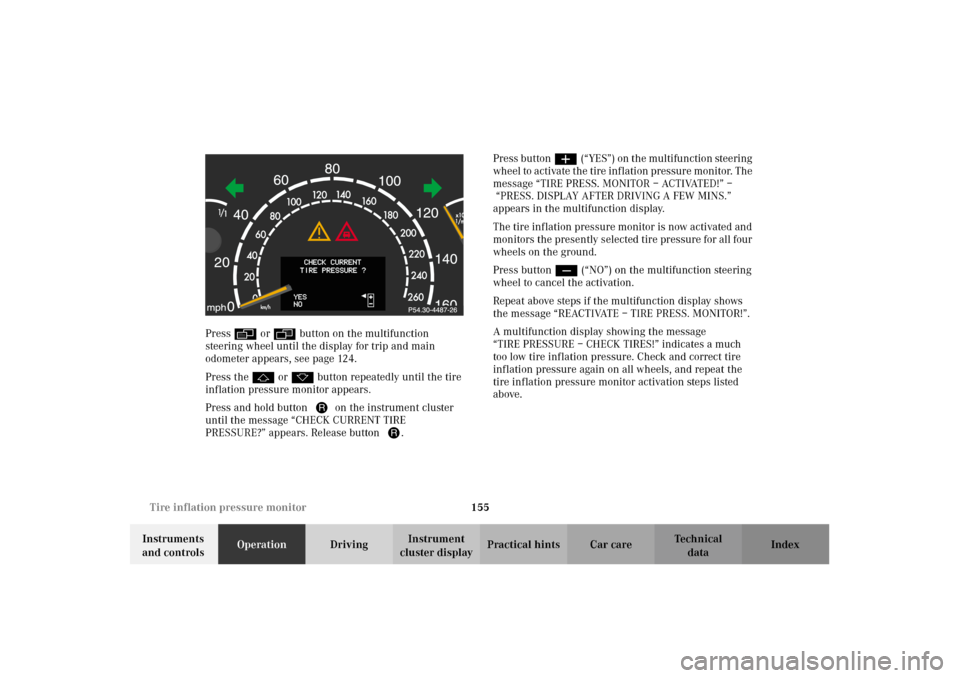
Press and hold button Jon the instrument cluster
until the message “CHECK CURRENT TIRE
PRESSURE?” appears. Release button J.Press buttonæ(“YES”) on the multifunction steering
whe el to activate t he tire inf lati on p res sur e mon itor. The
message “TIRE PRESS. MONITOR – ACTIVATED!” –
“PRESS. DISPLAY AFTER DRIVING A FEW MINS.”
appears in the multifunction display.
The tire inf lation pressure monitor is now activated and
monitors the presently selected tire pressure for all four
wheels on the ground.
Press buttonç(“NO”) on the multifunction steering
wheel to cancel the activation.
Repeat above steps if the multifunction display shows
the message “REACTIVATE – TIRE PRESS. MONITOR!”.
A multifunction display showing the message
“TIRE PRESSURE – CHECK TIRES!” indicates a much
too low tire inflation pressure. Check and correct tire
inflation pressure again on all wheels, and repeat the
tire inflation pressure monitor activation steps listed
above.
J_OM_215.book Seite 155 Mittwoch, 30. Mai 2001 2:01 14
Page 159 of 430

156 Tire inflation pressure monitor
Te ch n i c a l
data Instruments
and controlsOperationDrivingInstrument
cluster displayPractical hints Car care Index
Notes:
To ensure proper functioning of the tire inflation
pressure monitor, the tire inflation pressure should be
checked and corrected according to the label affixed
inside the fuel filler flap. For a detailed description,
refer to page 351.
The message “REACTIVATE – TIRE PRESS. MONITOR”
appears if the tire inflation pressure shows an increase
of 4.4 psi (0.3 bar) or more. Reactivate the tire inflation
pressure monitor.
The tire inflation pressure monitor only functions on
wheels equipped with the proper electronic sensors.
Inquire at your authorized Mercedes-Benz Center about
retrofitting other than original Mercedes-Benz wheels
with electronic sensors.
Transporting a deflated road wheel in the vehicle, e.g.
after having a flat, the tire inflation pressure monitor
should only be activated once the flat tire and rim are
removed from the vehicle.To prevent possible damage to the electronic sensors,
have tire changes only performed at an authorized
Mercedes-Benz Center.
For malfunction and warning messages, see page 318.
When checking the tire inflation pressure of the road
wheels, also check the spare tire.
The tire inflation pressure of the spare wheel, mounted
or not mounted, is not monitored by the tire inflation
pressure monitor.
See page 341 for location of the spare wheel, and
page 351 for tire inflation pressure.
J_OM_215.book Seite 156 Mittwoch, 30. Mai 2001 2:01 14
Page 160 of 430

157 Engine oil level indicator
Te ch n i c a l
data Instruments
and controlsOperationDrivingInstrument
cluster displayPractical hints Car care Index Engine oil level indicator
To check the engine oil level, park vehicle on level
ground, with engine at normal operational temperature.
Check oil level approximately 5 minutes after stopping
the engine, allowing for the oil to return to the oil pan.
The message “OBSERVE WAITING PERIOD” (perform
service [engine oil level check] on time) will be
displayed if the required waiting period has not been
observed after stopping the engine:
•with engine at operational temperature
approximately 5 minutes.•with engine not at operational temperature up to
approximately 30 minutes.
The engine oil level check can be repeated after a short
time.
Turn the electronic key in starter switch to position 2.
To call up the trip odometer and main odometer, press
buttonè orÿ on the multifunction steering
wheel until the display appears. See page 124.
Press buttonj ork on the multifunction
steering wheel repeatedly until the “CORRECT
MEASUREMENT ONLY – IF VEHICLE LEVEL” engine oil
level indicator appears. This indicator is only a
reminder. Measurement can be cancelled by pressing
buttonj ork if the vehicle is not parked on level
ground. An incorrect reading will be recorded if you do
not cancel the measurement. Move the vehicle to level
ground and measure again.
The electronic key in starter switch is not in position 2 if
the “ENGINE OIL LEVEL – IGNITION ON PLEASE”
message appears.
The “ENGINE OIL LEVEL – MEASUREMENT IN
PROCESS” message is displayed after approximately
3seconds.
J_OM_215.book Seite 157 Mittwoch, 30. Mai 2001 2:01 14
Page 167 of 430

164 Combination switch
Te ch n i c a l
data Instruments
and controlsOperationDrivingInstrument
cluster displayPractical hints Car care Index
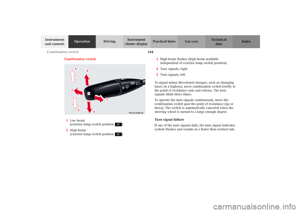
Combination switch
1Low beam
(exterior lamp switch positionB)
2High beam
(exterior lamp switch positionB)3High beam flasher (high beam available
independent of exterior lamp switch position)
4Turn signals, right
5Turn signals, left
To signal minor directional changes, such as changing
lanes on a highway, move combination switch briefly to
the point of resistance only and release. The turn
signals blink three times.
To operate the turn signals continuously, move the
combination switch past the point of resistance (up or
down). The switch is automatically canceled when the
steering wheel is turned to a large enough degree.
Turn signal failure
If one of the turn signals fails, the turn signal indicator
system flashes and sounds at a faster than normal rate.
P54.25-2388-26
5
2
1
4
3
4
5
J_OM_215.book Seite 164 Mittwoch, 30. Mai 2001 2:01 14
Page 172 of 430

169 Automatic climate control
Te ch n i c a l
data Instruments
and controlsOperationDrivingInstrument
cluster displayPractical hints Car care Index 1Center air outlet, left, adjustable
2Fixed air outlet, left
3Air volume control for left center air outlet
To open: Turn the thumbwheel upward.
�: The left center air outlet is fully open.
��: The left center and fixed air outlets are
opened.
4Air temperature control for center air outlets
To lower temperature: Turn thumbwheel towards
the blue marking.
Automatic mode: Turn thumbwheel to positionA.
The indicator lamp above the thumbwheel will
illuminate. The airflow and temperature for the
center air outlets are regulated automatically.
5Air volume control for right center air outlet.
To open: Turn the thumbwheel upward
�: The right center air outlet is fully open.
��: The right center and fixed air outlets are
opened.6Center air outlet, right, adjustable
7Fixed air outlet, right
8Side defroster outlet, left and right, fixed
9Side air outlet, left and right, adjustable
10Air volume control for side air outlets
To open: Turn thumbwheel outwards
�: The side air outlet is fully opened.
��: The side and door air outlets are opened.
11Door air outlet, left and right
12Display and controls
Note:
We recommend that the sliders for the air
outlets (1, 6, 9) be clicked to the automatic position to
provide practically draft free ventilation.
J_OM_215.book Seite 169 Mittwoch, 30. Mai 2001 2:01 14
Page 185 of 430
182 Automatic climate control
Te ch n i c a l
data Instruments
and controlsOperationDrivingInstrument
cluster displayPractical hints Car care Index
Rear passenger compartment adjustable air outlets 1Center air outlet, left
2Center air outlet, right
3Air volume control for center air outlets
To open: Turn the wheel to the left.
P83.00-2014-26
1
2
3
J_OM_215.book Seite 182 Mittwoch, 30. Mai 2001 2:01 14
Page 219 of 430

216 Tele Aid
Te ch n i c a l
data Instruments
and controlsOperationDrivingInstrument
cluster displayPractical hints Car care Index
Tele Aid
Important!
The initial activation of the Tele Aid system may only be
performed by completing the subscriber agreement and
placing an acquaintance call using the “SOS” button.
Failure to complete either of these steps will result in a
system that is not activated. If the system is not
activated the indicator lamp in the “SOS” button stays
on after turning electronic key in starter switch to
position 2 (vehicles with KEYLESS-GO:
operating position, see page 230) and the message
“TELE AID – NOT ACTIVATED” will be shown in the
multifunction display for approx. 10 seconds.
If you have any questions regarding activation, please
call the Response Center at 1-800-756-9018 (in the USA)
or 1-888-923-8367 (in Canada).
(Te l ematic Alarm Identification on Demand)
The Tele Aid system consists of three types of response;
automatic and manual emergency, roadside assistance
and information.
The Tele Aid system is operational providing that the
vehicle’s battery is charged, properly connected, not
damaged and cellular and GPS coverage is available.The speaker volume of a Tele Aid call can be adjusted
when using the volume control on the multifunction
steering wheel, for raising press buttonæ and for
lowering press buttonç.
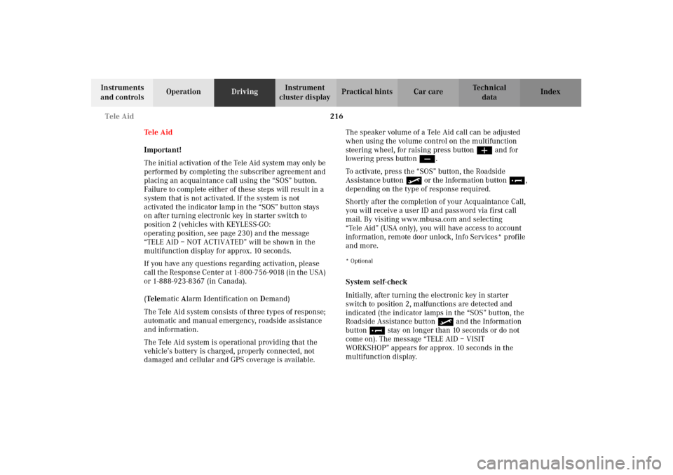
To activate, press the “SOS” button, the Roadside
Assistance button or the Information button¡,
depending on the type of response required.
Shortly after the completion of your Acquaintance Call,
you will receive a user ID and password via first call
mail. By visiting www.mbusa.com and selecting
“Tele Aid” (USA only), you will have access to account
information, remote door unlock, Info Services* profile
and more.
* Optional System self-check
Initially, after turning the electronic key in starter
switch to position 2, malfunctions are detected and
indicated (the indicator lamps in the “SOS” button, the
Roadside Assistance button and the Information
button¡ stay on longer than 10 seconds or do not
come on). The message “TELE AID – VISIT
WORKSHOP” appears for approx. 10 seconds in the
multifunction display.
J_OM_215.book Seite 216 Mittwoch, 30. Mai 2001 2:01 14