Page 92 of 390
89 Memory function
Te ch n i c a l
data Instruments
and controlsOperationDrivingInstrument
cluster displayPractical hints Car care Index Memory function
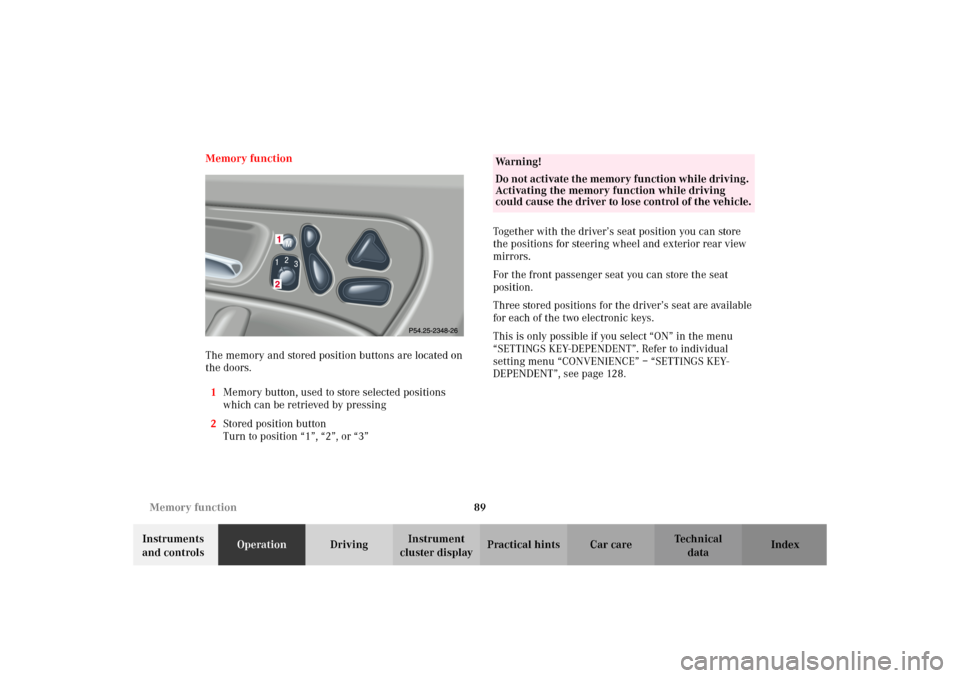
The memory and stored position buttons are located on
the doors.
1Memory button, used to store selected positions
which can be retrieved by pressing
2Stored position button
Turn to position “1”, “2”, or “3”Together with the driver’s seat position you can store
the positions for steering wheel and exterior rear view
mirrors.
For the front passenger seat you can store the seat
position.
Three stored positions for the driver’s seat are available
for each of the two electronic keys.
This is only possible if you select “ON” in the menu
“SETTINGS KEY-DEPENDENT”. Refer to individual
setting menu “CONVENIENCE” – “SETTINGS KEY-
DEPENDENT”, see page 128.
Wa r n i n g !
Do not activate the memory function while driving.
Activating the memory function while driving
could cause the driver to lose control of the vehicle.
S203.book Seite 89 Freitag, 19. Oktober 2001 1:25 13
Page 93 of 390
90 Memory function
Te ch n i c a l
data Instruments
and controlsOperationDrivingInstrument
cluster displayPractical hints Car care Index
Storing positions into memory:
With the electronic key in starter switch position 1 or 2
or with the relevant door open and the electronic key
inserted in the starter switch.
Adjust the seat to the desired position.
Driver’s seat:
You can also adjust the steering wheel and the exterior
rear view mirrors electrically for the driver’s seat. See
page 85 for exterior rear view mirror adjustment and
page 83 for steering wheel adjustment.
Turn button (2) to selected memory position.
Push memory button (1), release and push the position
button (2) within 3 seconds.Recalling positions from memory:
To recall a seat / steering wheel / exterior rear view
mirror position, turn button (2) to selected memory
position and press to recall.
The seat / steering wheel / exterior rear view mirror
movement stops when the button is released.
Caution!
Do not operate the power seats using the memory
button if the backrest is in an excessively reclined
position. Doing so could cause damage to front or rear
seats.
First move backrest to an upright position.
S203.book Seite 90 Freitag, 19. Oktober 2001 1:25 13
Page 94 of 390
91 Memory function
Te ch n i c a l
data Instruments
and controlsOperationDrivingInstrument
cluster displayPractical hints Car care Index Important!
Prior to operating the vehicle, the driver should check
and adjust if necessary the seat height, seat position
fore and aft, and backrest angle to insure adequate
control, reach and comfort. The head restraint should
also be adjusted for proper height. See also airbag
section for proper seat positioning.
In addition, also adjust the steering wheel to ensure
ad eq uate con tr ol, r each, operation and com fort. B ot h the
inside and outside rear view mirrors should be adjusted
for adequate rearward vision.
Fasten seat belts. Infants and small children should be
seated in a properly secured restraint system that
complies with U.S. Federal Motor Vehicle Safety
Standard 213 and Canadian Motor Vehicle Safety
Standard 213.
All seat, head restraint, steering wheel, and rear view
mirror adjustments as well as fastening of seat belts
should be done before the vehicle is put into motion.
Wa r n i n g !
Children 12 years old and under must never ride in
the front seat, except in a Mercedes-Benz
authorized BabySmart
TM compatible child seat,
which operates with the BabySmart
TM system
installed in the vehicle to deactivate the passenger
side front airbag when it is properly installed.
Otherwise they will be struck by the airbag when it
inflates in a crash. If this happens, serious or fatal
injury can result.
According to accident statistics, children are safer
when properly restrained in the rear seating
positions than in the front seating positions.
Infants and small children must ride in back seats
and be seated in an appropriate infant or child
restraint system, which is properly secured with
the vehicle’s seat belt, fully in accordance with the
child seat manufacturer’s instructions.A child’s risk of serious or fatal injuries is
significantly increased if the child restraints are
not properly secured in the vehicle and the child is
not properly secured in the child restraint.
S203.book Seite 91 Freitag, 19. Oktober 2001 1:25 13
Page 132 of 390
129 Multifunction steering wheel, multifunction display
Te ch n i c a l
data Instruments
and controlsOperationDrivingInstrument
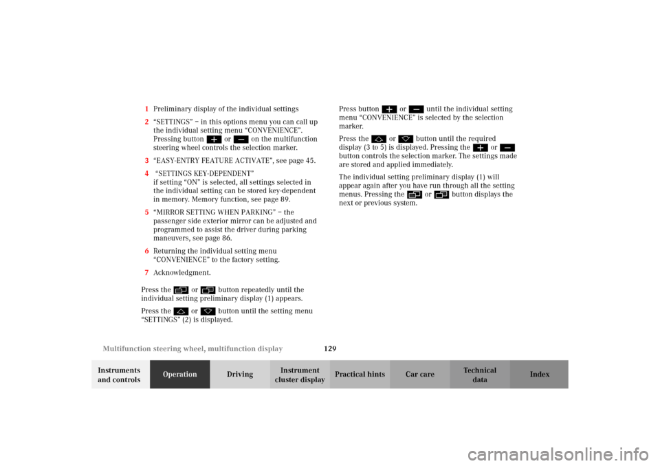
cluster displayPractical hints Car care Index 1Preliminary display of the individual settings
2“SETTINGS” – in this options menu you can call up
the individual setting menu “CONVENIENCE”.
Pressing buttonæ orç on the multifunction
steering wheel controls the selection marker.
3“EASY-ENTRY FEATURE ACTIVATE”, see page 45.
4 “SETTINGS KEY-DEPENDENT”
if setting “ON” is selected, all settings selected in
the individual setting can be stored key-dependent
in memory. Memory function, see page 89.
5“MIRROR SETTING WHEN PARKING” – the
passenger side exterior mirror can be adjusted and
programmed to assist the driver during parking
maneuvers, see page 86.
6Returning the individual setting menu
“CONVENIENCE” to the factory setting.
7Acknowledgment.
Press the è or ÿ button repeatedly until the
individual setting preliminary display (1) appears.
Press the j or k button until the setting menu
“SETTINGS” (2) is displayed.Press buttonæ orç until the individual setting
menu “CONVENIENCE” is selected by the selection
marker.
Press the j or k button until the required
display (3 to 5) is displayed. Pressing the æ orç
button controls the selection marker. The settings made
are stored and applied immediately.
The individual setting preliminary display (1) will
appear again after you have run through all the setting
menus. Pressing the è or ÿ button displays the
next or previous system.
S203.book Seite 129 Freitag, 19. Oktober 2001 1:25 13
Page 196 of 390
193 Interior equipment
Te ch n i c a l
data Instruments
and controlsOperationDrivingInstrument
cluster displayPractical hints Car care Index Sun visors
Swing sun visors (2) down (arrow 3) to protect against
sun glare.
If sunlight enters through a side window, disengage sun
visor (2) from the inner mounting (1) and pivot to the
side.Vanity mirrors
1Illuminated vanity mirror
With the visor engaged in its inner mounting (2),
the lamp (4) can be switched on by opening the
cover (3).
Fold the cover (3) down to close the vanity mirror.
Wa r n i n g !
Do not use the vanity mirror while driving.
S203.book Seite 193 Freitag, 19. Oktober 2001 1:25 13
Page 225 of 390
222 Garage door opener
Te ch n i c a l
data Instruments
and controlsOperationDrivingInstrument
cluster displayPractical hints Car care Index
For operation in the USA only: This device complies
with Part 15 of the FCC Rules. Operation is subject to
the following two conditions:
(1) This device may not cause harmful interference, and
(2) this device must accept any interference received,
including interference that may cause undesired
operation.
Any unauthorized modification to this device could void
the user’s authority to operate the equipment.Programming or reprogramming the integrated
remote control:
1. Turn electronic key in starter switch to position 1
or 2.
2. Hold the end of the hand-held transmitter of the
device you wish to train approximately 2 to 5 inches
(5 cm to 12 cm) away from the surface of the
integrated remote control located on the inside rear
view mirror, keeping the indicator lamp in view.
S203.book Seite 222 Freitag, 19. Oktober 2001 1:25 13
Page 232 of 390
229 Tele Aid
Te ch n i c a l
data Instruments
and controlsOperationDrivingInstrument
cluster displayPractical hints Car care Index Important!
Always make sure that the indicator lamps in the
“SOS” button, in the “Roadside Assistance” button and
in the “Information” button do not remain illuminated
constantly in red and the message “TELE AID – VISIT
WORKSHOP” is not displayed in the multifunction
display after the system self check.
If a malfunction is indicated as outlined above, have the
system checked at the nearest Mercedes-Benz Center as
soon as possible.
Emergency calls
An emergency call is initiated automatically:
•following an accident in which the Emergency
Tensioning Retractors (ETR’s) or airbags deploy,
•if the antitheft alarm or the tow-away alarm stays on
for more than 20 seconds, see pages 43 and 44.
An emergency call can also be initiated manually by
opening the cover next to the inside rear view mirror
labeled “SOS”, then briefly pressing the button located
under the cover. See below for instructions on initiating
an emergency call manually.Once the emergency call is in progress, the indicator
lamp in the “SOS” button will begin to flash. The
message “EMERGENCY CALL – CONNECTING CALL”
appears in the multifunction display. When the
connection is established, the message “EMERGENCY
CALL – CALL CONNECTED” appears in the
multifunction display. All information relevant to the
emergency, such as the location of the vehicle
(determined by the GPS satellite location system),
vehicle model, identification number and color are
generated.
A voice connection between the Response Center and
the occupants of the vehicle will be established
automatically soon after the emergency call has been
initiated. When a voice connection is established the
audio system mutes and the message “TELE AID –
EMERGENCY CALL ACTIVE” appears in the
multif un ction d isp lay. The Res pon se Cen ter will attemp t
to determine more precisely the nature of the accident
provided they can speak to an occupant of the vehicle.
S203.book Seite 229 Freitag, 19. Oktober 2001 1:25 13
Page 348 of 390
345 Exterior lamps
Te ch n i c a l
data Instruments
and controlsOperation DrivingInstrument
cluster displayPractical hintsCar care Index High mounted stop lamp,
Additional turn signals on the exterior mirror
The high mounted stop lamp (3rd brake lamp) is
equipped with LEDs. The additional turn signals on the
exterior mirrors are equipped with incandescent bulbs.
Have the system checked at an authorized
Mercedes-Benz Center if a malfunction occurs.Standby bulb function
The sto p lamp s, d im med , will act as a re placeme nt lamp ,
if one taillamp stops working.
The left stop lamp acts as a replacement for the rear fog
lamp, if it stops working.
The respective fog lamp, dimmed, will act as a
replacement lamp, if the left or right standing lamp
stops working.
Notes:
The multifunction display will indicate that a bulb has
failed. See malfunction and warning messages on
page 285.
S203.book Seite 345 Freitag, 19. Oktober 2001 1:25 13