2002 MERCEDES-BENZ C320 WAGON turn signal
[x] Cancel search: turn signalPage 173 of 390
170 Audio system
Te ch n i c a l
data Instruments
and controlsOperationDrivingInstrument
cluster displayPractical hints Car care Index
Storing stations
Hold the desired number button - down for
approximately 2 seconds. The currently displayed
frequency is stored on the selected station button. The
storage procedure is confirmed by a short signal tone.
Retrieving a station from memory
Press the desired station button - .
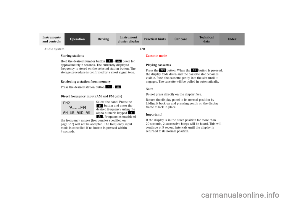
Direct frequency input (AM and FM only)
Select the band. Press the
“ button and enter the
desired frequency using the
alpha-numeric keypad -
. Frequencies outside of
the frequency ranges (frequencies specified on
page 167) will not be accepted. The frequency input
mode is cancelled if no button is pressed within
4seconds.Cassette mode
Playing cassettes
Pre ss t he button. When t he b utton is pr ess ed ,
the display folds down and the cassette slot becomes
visible. Push the cassette gently into the slot until it
engages. The cassette will be pulled in automatically.
Note:
Do not press directly on the display face.
Return the display panel to its normal position by
folding it back up and pressing gently on the display
frame to lock in place.
Important!
If the display is in the down position for more than
20 seconds, 2 successive beeps will be heard. This will
continue at 5 second intervals until the display is
returned to its normal position.
0OPR0OPR
0OPR
TAPE
EJ
S203.book Seite 170 Freitag, 19. Oktober 2001 1:25 13
Page 176 of 390
173 Audio system
Te ch n i c a l
data Instruments
and controlsOperationDrivingInstrument
cluster displayPractical hints Car care Index Scanning
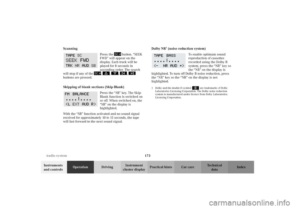
Press the button. “SEEK
FWD” will appear on the
display. Each track will be
played for 8 seconds in
ascending order. The search
will stop if any of the , , , ,
buttons are pressed.
Skipping of blank sections (Skip-Blank)
Press the “SB” key. The Skip-
Blank function is switched on
or off. When switched on, the
“SB” on the display is
highlighted.
With the “SB” function activated and no sound signal
received for approximately 10 to 15 seconds, the tape
will fast forward to the next sound signal.Dolby NR
1 (noise reduction system)
To enable optimum sound
reproduction of cassettes
recorded using the Dolby B
system, press the “NR” key so
the “NR” on the display is
highlighted. To turn off Dolby B noise reduction, press
the “NR” key so the “NR” on the display is not
highlighted.
1 Dolby and the double-D symbol
Ù
are trademarks of Dolby
Laboratories Licensing Corporation. The Dolby noise reduction
system is manufactured under licence from Dolby Laboratories
Licensing Corporation.
SC #
SC #
S203.book Seite 173 Freitag, 19. Oktober 2001 1:25 13
Page 227 of 390
224 Garage door opener
Te ch n i c a l
data Instruments
and controlsOperationDrivingInstrument
cluster displayPractical hints Car care Index
3. Firmly press and release the programmed
integrated remote control transmit button. Press
and release same button a second time to complete
the training process. (Some garage door openers
may required you to do this procedure a third time
to complete the training.)
4. Confirm the garage door operation by pressing the
programmed button on the integrated remote
control transmitter.
Canadian programming:
During programming, your hand-held transmitter may
automatically stop transmitting. Continue to press and
hold the integrated remote control transmitter button
(note steps 2 through 4 in the “Programming” portion)
while you press and re-press (“cycle”) your hand-held
transmitter every two seconds until the frequency
signal has been learned. The indicator lamp will flash
slowly and then rapidly after several seconds upon
successful training.Operation of remote control:
1. Turn electronic key in starter switch to position 1
or 2.
2. Select and press the appropriate button to activate
the remote control device. The integrated remote
control transmitter continues to send the signal as
long as the button is pressed – up to 20 seconds.
Erasing the remote control memory:
1. Turn electronic key in starter switch to position 1
or 2.
2. Simultaneously holding down the left and right side
buttons for approximately 20 seconds, or until the
control lamp blink rapidly, will erase the codes of all
three channels.
S203.book Seite 224 Freitag, 19. Oktober 2001 1:25 13
Page 236 of 390
233 Tele Aid
Te ch n i c a l
data Instruments
and controlsOperationDrivingInstrument
cluster displayPractical hints Car care Index Notes:
The indicator lamp in the Roadside Assistance
button remains illuminated in red for approx.
10 seconds during the system self-check after turning
electronic key in starter switch to position 2 (together
with the “SOS” button and the Information
button¡).
See system self-check on page 228 when the indicator
lamp does not light up in red or stays on longer than
approximately 10 seconds.
If the indicator lamp in the Roadside Assistance
button is illuminated continuously and there was
no voice connection to the Response Center established,
then the Tele Aid system could not initiate an Roadside
Assistance call (e.g. the relevant cellular phone network
is not available). The message “ROADSIDE
ASSISTANCE – CALL FAILED” appears in the
multifunction display.
Roadside Assistance calls can be terminated using the
ìbutton on the multifunction steering wheel.Information button ¡
Located below the center armrest cover is the
Information button¡. Pressing and holding the
button (for longer than 2 seconds) will initiate a call to
the Customer Assistance Center. The button will flash
while the call is in progress. The message “INFO –
CONNECTING CALL” will appear in the multifunction
display. When the connection is established, the
message “INFO – CALL CONNECTED” appears in the
multifunction display. The Tele Aid system will transmit
data generating the vehicle identification number,
model, color and location (subject to availability of
cellular and GPS signals).
A voice connection between the Customer Assistance
Center representative and the occupants of the vehicle
will be established. When a voice connection is
established the audio system mutes and the message
“TELE AID – INFO CALL ACTIVE” appears in the
multifunction display. Information regarding the
operation of your vehicle, the nearest Mercedes-Benz
Center or Mercedes-Benz USA products and services is
ava il ab le to yo u .
For more details concerning Tele Aid, please visit
www.mbusa.com and use your ID and password, sent to
you separately, to learn more (USA only).
S203.book Seite 233 Freitag, 19. Oktober 2001 1:25 13
Page 237 of 390
234 Tele Aid
Te ch n i c a l
data Instruments
and controlsOperationDrivingInstrument
cluster displayPractical hints Car care Index
Notes:
The indicator lamp in the Information button¡
remains illuminated in red for approx. 10 seconds
during the system self-check after turning electronic
key in starter switch to position 2 (together with the
“SOS” button and the Roadside Assistance button).
See system self-check on page 228 when the indicator
lamp does not light up in red or stays on longer than
approximately 10 seconds.
If the indicator lamp in the Information button¡ is
illuminated continuously and there was no voice
connection to the Response Center established, then the
Tele Aid system could not initiate an Information call
(e.g. the relevant cellular phone network is not
available). The message “INFO – CALL FAILED” appears
in the multifunction display.
Information calls can be terminated using the
ìbutton on the multifunction steering wheel.Important!
If the indicator lamps do not start flashing after
pressing one of the buttons or remain illuminated (in
red) at any time, the Tele Aid system has detected a fault
or the service is not currently active, and may not
initiate a call.
Visit your Mercedes-Benz Center and have the system
checked or contact the Response Center at 1-800-756-
9018 (in the USA) or 1-888-923-8367 (in Canada) as
soon as possible.
Upgrade Signals
Tele Aid system processes calls using the following
priority.
•Automatic emergency – First priority
•Manual emergency – Second priority
•Roadside assistance – Third priority
•Information – Fourth priority
Should a higher priority call be initiated while you are
connected, an upgrade (alternating) tone will be heard,
and the appropriate indicator lamp will flash. If certain
information such as vehicle identification number or
customer information is not available, the operator may
S203.book Seite 234 Freitag, 19. Oktober 2001 1:25 13
Page 278 of 390
275 What you should know at the gas station
Te ch n i c a l
data Instruments
and controlsOperationDrivingInstrument
cluster displayPractical hints Car care Index Fuel tank capacity approximately 16.4 US gal (62.0 l).
This includes approximately 2.1 US gal (8.0 l) reserve.
Use premium unleaded gasoline:
Posted Octane Index 91 (Average of 96 RON / 86 MON).
Engine oil
Checking oil level, see instructions on page 135 and 314.
Recommended engine oils, see Approved Service
Products sheet.
Coolant
For normal replenishing, use water (potable water
quality). For further information refer to page 315.
Tire pressure
For tire pressure, refer to tire pressure label inside the
fuel filler flap. See page 329 for further details.Spark plugs
Approved spark plugs, refer to “Technical Data”.
Air conditioner
R-134a refrigerant and special PAG lubricant, refer to
“Technical Data”.
Bulbs
High and low beams: H7 (55 W),
low beam: Xenon (optional)
fog lamps: H B4 (55 W),
turn signal lamps,
front: 1156 NA (26.9 / 5 W/32/4 cp),
parking and standing lamps, front: W 5W (5 W)
side marker lamps, front: 5 W / 4 cp,
turn signal lamps, rear: PY 21 W bulb (yellow),
stop lamps: P 21 W/32 cp bulb,
rear fog lamp (driver’s side)/tail, parking, standing and
side marker lamp: P 21/4 W
backup lamps: P 21 W / 32 cp,
license plate lamps: 5 W / 4 cp
S203.book Seite 275 Freitag, 19. Oktober 2001 1:25 13
Page 300 of 390
297 Malfunction and warning messages
Te ch n i c a l
data Instruments
and controlsOperation DrivingInstrument
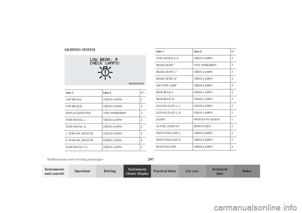
cluster displayPractical hints Car care Index LIGHTING SYSTEM
Line 1 Line 2 C*
LOW BEAM,L CHECK LAMPS! 2
LOW BEAM,R CHECK LAMPS! 2
DISPLAY DEFECTIVE VISIT WORKSHOP!
1
2
TURN SIGNAL, L CHECK LAMPS! 2
TURN SIGNAL, R CHECK LAMPS! 2
L. TURN SIG. RFLECTR CHECK LAMPS! 2
R. TURN SIG. RFLECTR CHECK LAMPS! 2
TURN SIGNAL F, L CHECK LAMPS! 2
TURN SIGNAL F, R CHECK LAMPS! 2
BRAKE LIGHT
2
VISIT WORKSHOP! 2
BRAKE LIGHT, L
3
CHECK LAMPS! 2
BRAKE LIGHT, R
3
CHECK LAMPS! 2
3RD STOP LAMP
3
CHECK LAMPS! 2
HIGH BEAM, L CHECK LAMPS! 2
HIGH BEAM, R CHECK LAMPS! 2
LICENSE PLATE L, L CHECK LAMPS! 2
LICENSE PLATE L, R CHECK LAMPS! 2
LIGHTS SWITCH OFF LIGHTS! 1
AUTOM. LIGHT ON REMOVE KEY! 1
FRONT FOGLAMP, L CHECK LAMPS! 2
FRONT FOGLAMP, R CHECK LAMPS! 2
REAR FOGLAMP CHECK LAMPS! 2 Line 1 Line 2 C*
S203.book Seite 297 Freitag, 19. Oktober 2001 1:25 13
Page 340 of 390
337 Towing the vehicle
Te ch n i c a l
data Instruments
and controlsOperation DrivingInstrument
cluster displayPractical hintsCar care Index We recommend that the vehicle be transported using
flat bed equipment. This method is preferable to other
types of towing.
Important!
To prevent damage during transport, do not tie down
vehicle by its chassis or suspension parts.
Towing restrictions for vehicles with automatic
transmission:
The vehicle may be towed with all wheels on the ground
and the selector lever in position “N” for distances up to
30 miles (50 km) and at a speed not to exceed 30 mph
(50 km / h). The electronic key must be in starter switch
position 2.
To be certain to avoid a possibility of damage to the
transmission, however, we recommend the drive shaft
be disconnected at the rear axle drive flange for any
towing beyond a short tow to a nearby garage.
Do not tow with sling-type equipment. Towing with
sling-type equipment over bumpy roads will damage
radiator and supports.
Use wheel lift, dolly, or flat bed equipment, with
electronic key in starter switch turned to position 0.Note:
To signal turns while being towed with hazard warning
flasher in use, turn electronic key in starter switch to
position 2 and activate combination switch for left or
right turn signal in usual manner – only the selected
turn signal will operate.
Upon canceling the turn signal, the hazard warning
flasher will operate again.
Caution!
If the vehicle is towed with the front axle raised, the
engine must be shut off (electronic key in starter switch
position 0 or 1). Otherwise, the ESP will immediately be
engaged and will apply the rear wheel brakes.
Switch off the tow-away alarm (see page 44) as well as
the ESP (see page 270).
Wa r n i n g !
With the engine not running, there is no power
assistance for the braking and steering systems. In
this case, it is important to keep in mind that a
considerably higher degree of effort is necessary to
brake and steer the vehicle.
S203.book Seite 337 Freitag, 19. Oktober 2001 1:25 13