Page 97 of 406

94 Rear view mirrors
Te ch n i c a l
data Instruments
and controlsOperationDrivingInstrument
cluster displayPractical hints Car care Index
Driver’s side exterior rear view mirror,
antiglare mode
With the electronic key in starter switch position 2, the
mirror reflection brightness responds to changes in
light sensitivity.
With the gear selector lever in position “R”, or with the
interior light switched on, the mirror brightness does
not respond to changes in light sensitivity.
Note:
The automatic antiglare function does not react, if
incoming light is not aimed directly at sensors in the
inside rear view mirror.
The automatic antiglare function will not react for
example, if the rear window sun shade is in the raised
position.Important!
Electrolyte drops coming into contact with the vehicle
paint finish can only be completely removed while in
their liquid state, by applying plenty of water.
Wa r n i n g !
In the case of an accident liquid electrolyte may
escape the mirror housing when the mirror glass
breaks.Electrolyte has an irritating effect. Do not allow the
liquid to come into contact with eyes, skin,
clothing, or respiratory system. In cases it does,
immediately flush affected area with water, and
seek medical help if necessary.
OM_203.book Seite 94 Donnerstag, 31. Mai 2001 11:57 11
Page 98 of 406

95 Memory function
Te ch n i c a l
data Instruments
and controlsOperationDrivingInstrument
cluster displayPractical hints Car care Index Memory function
(model C 320 only, optional on model C 240)
The memory and stored position buttons are located on
the doors.
1Memory button, used to store selected positions
which can be retrieved by pressing
2Stored position button
Turn to position “1”, “2”, or “3”Together with the driver’s seat position you can store
the positions for steering wheel and exterior rear view
mirrors.
For the front passenger seat you can store the seat
position.
Three stored positions for the driver’s seat are available
for each of the two electronic keys.
This is only possible if you select “ON” in the menu
“SETTINGS KEY-DEPENDENT”. Refer to individual
setting menu “CONVENIENCE” – “SETTINGS KEY-
DEPENDENT”, see page 134.
Wa r n i n g !
Do not activate the memory function while driving.
Activating the memory function while driving
could cause the driver to lose control of the vehicle.
OM_203.book Seite 95 Donnerstag, 31. Mai 2001 11:57 11
Page 99 of 406

96 Memory function
Te ch n i c a l
data Instruments
and controlsOperationDrivingInstrument
cluster displayPractical hints Car care Index
Storing positions into memory:
With the electronic key in starter switch position 1 or 2
or with the relevant door open and the electronic key
inserted in the starter switch.
Adjust the seat to the desired position.
Driver’s seat:
You can also adjust the steering wheel and the exterior
rear view mirrors electrically for the driver’s seat. See
page 91 for exterior rear view mirror adjustment and
page 89 for steering wheel adjustment.
Turn button (2) to selected memory position.
Push memory button (1), release and push the position
button (2) within 3 seconds.Recalling positions from memory:
To recall a seat / steering wheel / exterior rear view
mirror position, turn button (2) to selected memory
position and press to recall.
The seat / steering wheel / exterior rear view mirror
movement stops when the button is released.
Caution!
Do not operate the power seats using the memory
button if the backrest is in an excessively reclined
position. Doing so could cause damage to front or rear
seats.
First move backrest to an upright position.
OM_203.book Seite 96 Donnerstag, 31. Mai 2001 11:57 11
Page 100 of 406

97 Memory function
Te ch n i c a l
data Instruments
and controlsOperationDrivingInstrument
cluster displayPractical hints Car care Index Important!
Prior to operating the vehicle, the driver should check
and adjust if necessary the seat height, seat position
fore and aft, and backrest angle to insure adequate
control, reach and comfort. The head restraint should
also be adjusted for proper height. See also airbag
section for proper seat positioning.
In addition, also adjust the steering wheel to ensure
ad eq uate con tr ol, r each, operation and com fort. B ot h the
inside and outside rear view mirrors should be adjusted
for adequate rearward vision.
Fasten seat belts. Infants and small children should be
seated in a properly secured restraint system that
complies with U.S. Federal Motor Vehicle Safety
Standard 213 and Canadian Motor Vehicle Safety
Standard 213.
All seat, head restraint, steering wheel, and rear view
mirror adjustments as well as fastening of seat belts
should be done before the vehicle is put into motion.
Wa r n i n g !
Children 12 years old and under must never ride in
the front seat, except in a Mercedes-Benz
authorized BabySmart
TM compatible child seat,
which operates with the BabySmart
TM system
installed in the vehicle to deactivate the passenger
side front airbag when it is properly installed.
Otherwise they will be struck by the airbag when it
inflates in a crash. If this happens, serious or fatal
injury can result.
According to accident statistics, children are safer
when properly restrained in the rear seating
positions than in the front seating positions.
Infants and small children must ride in back seats
and be seated in an appropriate infant or child
restraint system, which is properly secured with
the vehicle’s seat belt, fully in accordance with the
child seat manufacturer’s instructions.A child’s risk of serious or fatal injuries is
significantly increased if the child restraints are
not properly secured in the vehicle and the child is
not properly secured in the child restraint.
OM_203.book Seite 97 Donnerstag, 31. Mai 2001 11:57 11
Page 101 of 406
98 Instrument cluster
Te ch n i c a l
data Instruments
and controlsOperationDrivingInstrument
cluster displayPractical hints Car care Index
Instrument cluster
OM_203.book Seite 98 Donnerstag, 31. Mai 2001 11:57 11
Page 102 of 406

99 Instrument cluster
Te ch n i c a l
data Instruments
and controlsOperationDrivingInstrument
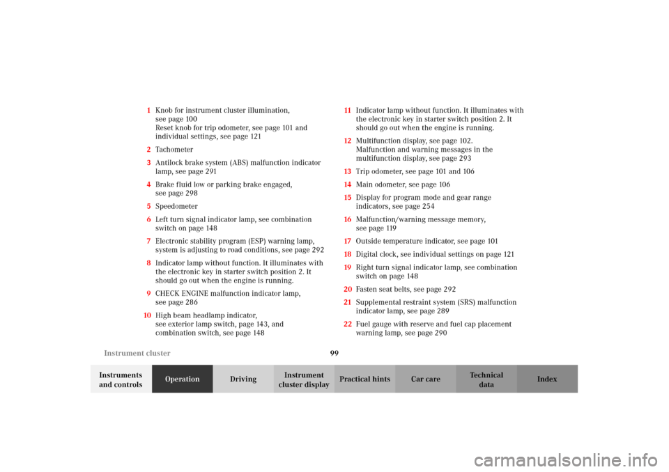
cluster displayPractical hints Car care Index 1Knob for instrument cluster illumination,
seepage100
Reset knob for trip odometer, see page 101 and
individual settings, see page 121
2Tachometer
3Antilock brake system (ABS) malfunction indicator
lamp, see page 291
4Brake fluid low or parking brake engaged,
seepage298
5Speedometer
6Left turn signal indicator lamp, see combination
switch on page 148
7Electronic stability program (ESP) warning lamp,
system is adjusting to road conditions, see page 292
8Indicator lamp without function. It illuminates with
the electronic key in starter switch position 2. It
should go out when the engine is running.
9CHECK ENGINE malfunction indicator lamp,
seepage286
10High beam headlamp indicator,
seeexterior lamp switch, page143, and
combination switch, see page 14811Indicator lamp without function. It illuminates with
the electronic key in starter switch position 2. It
should go out when the engine is running.
12Multifunction display, see page 102.
Malfunction and warning messages in the
multifunction display, see page 293
13Trip odometer, see page 101 and 106
14Main odometer, see page 106
15Display for program mode and gear range
indicators, see page 254
16Malfunction/warning message memory,
seepage119
17Outside temperature indicator, see page 101
18Digital clock, see individual settings on page 121
19Right turn signal indicator lamp, see combination
switch on page 148
20Fasten seat belts, see page 292
21Supplemental restraint system (SRS) malfunction
indicator lamp, see page 289
22Fuel gauge with reserve and fuel cap placement
warning lamp, see page 290
OM_203.book Seite 99 Donnerstag, 31. Mai 2001 11:57 11
Page 103 of 406

100 Instrument cluster
Te ch n i c a l
data Instruments
and controlsOperationDrivingInstrument
cluster displayPractical hints Car care Index
Activating instrument cluster display
The instrument cluster is activated by:
•Opening the door
1.
•Pressing button (1) on the instrument cluster
1.
•Turning the electronic key in starter switch to
position 1 or 2.
•Switching on the exterior lamps.
Instrument cluster illumination
The instrument cluster illumination is dimmed or
brightened automatically to suit daylight lighting
conditions.
The instrument cluster illumination will also be
adjusted when the vehicle’s exterior lamps are switched
on.
1 The instrument cluster is activated for approximately 30 seconds.
Display illumination, changing basic settings for driving
at dusk or in darkness:
Rotate adjusting knob (1) clockwise – instrument lamp
intensity increases.
Rotate adjusting knob (1) counterclockwise –
instrument lamp intensity decreases.
Note:
It is not possible to select a basic brightness setting in
daylight – the intensity is adjusted automatically.
OM_203.book Seite 100 Donnerstag, 31. Mai 2001 11:57 11
Page 104 of 406

101 Instrument cluster
Te ch n i c a l
data Instruments
and controlsOperationDrivingInstrument
cluster displayPractical hints Car care Index Outside temperature indicator (17)
The temperature sensor is located in the front bumper
area. Due to its location, the sensor can be affected by
road or engine heat during idling or slow driving. This
means that the accuracy of the displayed temperature
can only be verified by comparison to a thermometer
placed next to the sensor, not by comparison to external
displays (e.g. bank signs etc.).
Adaption to ambient temperature takes place in steps
and depends on the prevailing driving conditions (stop-
and-go or moderate, constant driving) and amount of
temperature change.
Note:
The uni t for the temp erature in di cator d is play can b e set
in the individual setting menu “INSTRUMENT
CLUSTER” – “TEMP. INDICATOR” on page 121.Trip odometer (13)
To reset to “0” miles / km:
Activate the instrument cluster if it is not already
activated, see page 100.
Press button è or ÿ on the multifunction
steering wheel repeatedly until the trip odometer
appears if it is not displayed. See page 106.
Press button (1) on the instrument cluster, see page 100.
Tachometer (2)
The red marking on the tachometer denotes excessive
engine speed.
Avoid this engine speed, as it may result in serious
engine damage that is not covered by the
Mercedes-Benz Limited Warranty.
To help protect the engine, the fuel supply is interrupted
if the engine is operated within the red marking.
Wa r n i n g !
The outside temperature indicator is not designed
to serve as an Ice-Warning Device and is therefore
unsuitable for that purpose. Indicated
temperatures just above the freezing point do not
guarantee that the road surface is free of ice.
OM_203.book Seite 101 Donnerstag, 31. Mai 2001 11:57 11