2002 MERCEDES-BENZ C240 warning
[x] Cancel search: warningPage 30 of 406

27 Contents - Operation
Te ch n i c a l
data Instruments
and controlsOperationDrivingInstrument
cluster displayPractical hints Car care Index Malfunction/warning
message memory .......................119
Individual settings ......................... 121
Setting the audio volume .............. 136
Coolant temperature gauge .......... 137
Flexible service system
(FSS) ............................................ 138
Engine oil level indicator .............. 141
Engine oil consumption ................ 142
Exterior lamp switch ..................... 143
Headlamp mode ............................. 144
Night security illumination ......... 146
Locator lighting .......................... 147
Headlamp cleaning system .......... 147
Combination switch ...................... 148
Hazard warning flasher
switch .......................................... 151Climate control ...............................152
Automatic climate control .............160
Front center console storage
compartment ventilation .......... 171
Rear passenger compartment
adjustable air outlets ............... 172
Operation Audio and telephone .. 173
Operating safety ............................ 173
Operating and display elements .. 174
Button and soft key operation ...... 176
Component malfunctions ..............195
Power windows ...............................197
Sliding/pop-up roof ....................... 200
Interior lighting ............................. 203
Rear window sunshade ................ 205
Sun visors ....................................... 206
Vanity mirrors ............................... 206Interior ............................................207
Storage compartments
and armrests ..............................207
Glove box .....................................208
Cup holder ...................................... 211
Ashtrays .......................................... 213
Lighter ............................................. 215
Parcel net in
front passenger footwell .......... 216
Ski sack ........................................... 216
Enlarged cargo area ....................... 221
Split folding rear seat bench ........ 221
Loading instructions
(vehicle with
enlarged cargo area) .................223
Cellular telephone .........................224
Telephone, general ........................225
Garage door opener .......................226
OM_203.book Seite 27 Donnerstag, 31. Mai 2001 11:57 11
Page 67 of 406

64 Restraint systems
Te ch n i c a l
data Instruments
and controlsOperationDrivingInstrument
cluster displayPractical hints Car care Index
Seat belt nonusage warning system
With the electronic key in starter switch position 2, a
warning sounds for a short time if the driver’s seat belt
is not fastened.
Automatic comfort-fit seat belt:
An automatic comfort-fit feature for driver and front
passenger seat belt is activated when the electronic key
in the starter switch is turned to position 1 or 2.
The retraction force of the inertia reel is reduced,
increasing the level of seat belt comfort.
Note:
For cleaning and care of the seat belts see page 371.
Wa r n i n g !
Never ride in a moving vehicle with the backrest
reclined. Sitting in an excessively reclined position
can be dangerous. You could slide under the seat
belt in a collision. If you slide under it, the belt
would apply force at the abdomen or neck. That
could cause serious or even fatal injuries. The
backrest and seat belt provide the best restraint
when the wearer is in an upright position and the
belt is properly positioned on the body.
OM_203.book Seite 64 Donnerstag, 31. Mai 2001 11:57 11
Page 86 of 406

83 Restraint systems
Te ch n i c a l
data Instruments
and controlsOperationDrivingInstrument
cluster displayPractical hints Car care Index Infant and child restraint systems
We recommend all infants and children be properly
restrained at all times while the vehicle is in motion. All
lap-shoulder belts except the driver seat belt have
special seat belt retractors for secure fastening of child
restraints.
To activate, pull shoulder belt out completely and let it
retract. During the seat belt retraction a ratcheting
sound can be heard to indicate that the special seat belt
retractor is activated. The belt is now locked.
To deactivate, release seat belt buckle and let seat belt
retract completely. The seat belt can again be used in
the usual manner.
Note:
For child seats with mounting fittings for tether
anchorages refer to page 85 (installation of infant and
child restraint systems).Important!
The use of infant or child restraints is required by law in
all 50 states and all Canadian provinces.
Infants and small children should be seated in an
appropriate infant or child restraint system properly
secured by a lap-shoulder belt, and that complies with
U.S. Federal Motor Vehicle Safety Standard 213 and
Canadian Motor Vehicle Safety Standard 213.
A statement by the child restraint manufacturer of
compliance with this standard can be found on the
instruction label on the restraint and in the instruction
manual provided with the restraint.
When using any infant or child restraint system, be sure
to carefully read and follow all manufacturer’s
instructions for installation and use.
Please read and observe warning labels affixed to inside
of vehicle and to infant or child restraints.
Wa r n i n g !
Never release the seat belt buckle while vehicle is
in motion, since the special seat belt retractor will
be deactivated.
OM_203.book Seite 83 Donnerstag, 31. Mai 2001 11:57 11
Page 91 of 406

88 Restraint systems
Te ch n i c a l
data Instruments
and controlsOperationDrivingInstrument
cluster displayPractical hints Car care Index
Steering wheel adjustment (manual)Unlocking:
Pull handle (1) out to its stop.
Adjusting:
Move steering wheel to the desired position.
Locking:
Push handle (1) in until it engages.
Important!
Do not drive the vehicle until you have properly locked
the steering column.
See “STEERING WHEEL ADJUST” on page 312 for
malfunction and warning messages in the multifunction
display.
Wa r n i n g !
Do not adjust the steering wheel while driving.
Adjusting the steering wheel while driving, or
driving without the adjustment locked could cause
the driver to lose control of the vehicle.
P 68.10-2066-27
OM_203.book Seite 88 Donnerstag, 31. Mai 2001 11:57 11
Page 102 of 406

99 Instrument cluster
Te ch n i c a l
data Instruments
and controlsOperationDrivingInstrument
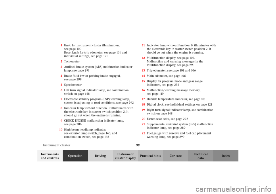
cluster displayPractical hints Car care Index 1Knob for instrument cluster illumination,
seepage100
Reset knob for trip odometer, see page 101 and
individual settings, see page 121
2Tachometer
3Antilock brake system (ABS) malfunction indicator
lamp, see page 291
4Brake fluid low or parking brake engaged,
seepage298
5Speedometer
6Left turn signal indicator lamp, see combination
switch on page 148
7Electronic stability program (ESP) warning lamp,
system is adjusting to road conditions, see page 292
8Indicator lamp without function. It illuminates with
the electronic key in starter switch position 2. It
should go out when the engine is running.
9CHECK ENGINE malfunction indicator lamp,
seepage286
10High beam headlamp indicator,
seeexterior lamp switch, page143, and
combination switch, see page 14811Indicator lamp without function. It illuminates with
the electronic key in starter switch position 2. It
should go out when the engine is running.
12Multifunction display, see page 102.
Malfunction and warning messages in the
multifunction display, see page 293
13Trip odometer, see page 101 and 106
14Main odometer, see page 106
15Display for program mode and gear range
indicators, see page 254
16Malfunction/warning message memory,
seepage119
17Outside temperature indicator, see page 101
18Digital clock, see individual settings on page 121
19Right turn signal indicator lamp, see combination
switch on page 148
20Fasten seat belts, see page 292
21Supplemental restraint system (SRS) malfunction
indicator lamp, see page 289
22Fuel gauge with reserve and fuel cap placement
warning lamp, see page 290
OM_203.book Seite 99 Donnerstag, 31. Mai 2001 11:57 11
Page 104 of 406

101 Instrument cluster
Te ch n i c a l
data Instruments
and controlsOperationDrivingInstrument
cluster displayPractical hints Car care Index Outside temperature indicator (17)
The temperature sensor is located in the front bumper
area. Due to its location, the sensor can be affected by
road or engine heat during idling or slow driving. This
means that the accuracy of the displayed temperature
can only be verified by comparison to a thermometer
placed next to the sensor, not by comparison to external
displays (e.g. bank signs etc.).
Adaption to ambient temperature takes place in steps
and depends on the prevailing driving conditions (stop-
and-go or moderate, constant driving) and amount of
temperature change.
Note:
The uni t for the temp erature in di cator d is play can b e set
in the individual setting menu “INSTRUMENT
CLUSTER” – “TEMP. INDICATOR” on page 121.Trip odometer (13)
To reset to “0” miles / km:
Activate the instrument cluster if it is not already
activated, see page 100.
Press button è or ÿ on the multifunction
steering wheel repeatedly until the trip odometer
appears if it is not displayed. See page 106.
Press button (1) on the instrument cluster, see page 100.
Tachometer (2)
The red marking on the tachometer denotes excessive
engine speed.
Avoid this engine speed, as it may result in serious
engine damage that is not covered by the
Mercedes-Benz Limited Warranty.
To help protect the engine, the fuel supply is interrupted
if the engine is operated within the red marking.
Wa r n i n g !
The outside temperature indicator is not designed
to serve as an Ice-Warning Device and is therefore
unsuitable for that purpose. Indicated
temperatures just above the freezing point do not
guarantee that the road surface is free of ice.
OM_203.book Seite 101 Donnerstag, 31. Mai 2001 11:57 11
Page 122 of 406

119 Multifunction steering wheel, multifunction display
Te ch n i c a l
data Instruments
and controlsOperationDrivingInstrument
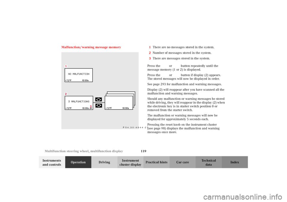
cluster displayPractical hints Car care Index Malfunction / warning message memory 1There are no messages stored in the system.
2Number of messages stored in the system.
3There are messages stored in the system.
Press the è or ÿ button repeatedly until the
message memory (1 or 2) is displayed.
Press the j or k button if display (2) appears.
The stored messages will now be displayed in order.
See page 293 for malfunction and warning messages.
Display (2) will reappear after you have scanned all the
malfunction and warning messages.
Should any malfunction or warning messages be stored
while driving, they will reappear in the display (2) when
the electronic key is in starter switch position 0 or
removed from the starter switch.
The malfunction or warning messages will now be
displayed for approximately 5 seconds each.
Pressing the reset knob on the instrument cluster
(see page 98) displays the malfunction and warning
messages once more.
P 54.30-4644-27
OM_203.book Seite 119 Donnerstag, 31. Mai 2001 11:57 11
Page 123 of 406

120 Multifunction steering wheel, multifunction display
Te ch n i c a l
data Instruments
and controlsOperationDrivingInstrument
cluster displayPractical hints Car care Index
The message memory will be cleared when the
electronic key is turned in the starter switch to
position 1 or 2. Should any subsequent faults occur,
they will be displayed in the message memory.
Pressing the è or ÿ button displays the next or
previous system.Important!
Malfunction and warning messages are only indicated
for certain systems and displayed to a low level of detail.
The malfunction and warning messages are simply a
reminder with respect to the operation of certain
systems and do not replace the driver’s responsibility to
maintain the vehicle’s operating safety by having all
required maintenance and safety checks performed on
the vehicle and by bringing the vehicle to an authorized
Mercedes-Benz Center to address the malfunction and
warning messages. See page 293, for malfunction and
warning messages.
OM_203.book Seite 120 Donnerstag, 31. Mai 2001 11:57 11