Page 329 of 399

326 Tires, Wheels
Te ch n i c a l
data Instruments
and controlsOperation DrivingInstrument
cluster displayPractical hintsCar care Index
Spare wheel
Important!
The spare wheel rim size is 4
1/2 Bx15H2 with
inflatable, collapsible tire, size 165 -15 89 P.
You should inflate the spare tire using the supplied air
pump.
In the case of a flat tire, you may temporarily use the
spare wheel, while observing the following restrictions:
•Do not exceed vehicle speed of 50 mph (80 km / h).
•Drive to the nearest tire repair facility to have the
flat tire repaired or replaced as appropriate.
•Do not operate vehicle with more than one
collapsible spare wheel / tire mounted.
For additional information, refer to page 374.
Wa r n i n g !The dimensions of the spare wheel are different
from those of the road wheels. As a result, the
vehicle handling characteristics change when
driving with a mounted spare wheel.The spare wheel should only be used temporarily,
and replaced with a regular road wheel as quick as
possible.
Page 331 of 399
328 Tires, Wheels
Te ch n i c a l
data Instruments
and controlsOperation DrivingInstrument
cluster displayPractical hintsCar care Index
4. Remove the two-piece wheel wrench from the
vehicle tool kit and assemble (see page 323).
5. Using the wrench, loosen but do not yet remove the
wheel bolts.6. Place jack on firm ground. Position jack (1) under
the take-up bracket (2) so that it is always vertical
(plumb-line) as seen from the side, even if the
vehicle is parked on an incline.
The jack take-up brackets are located directly
behind the front wheel housings and in front of the
rear wheel housings.
7. Jack up the vehicle until the wheel is clear of the
ground. Never start engine while vehicle is raised.
P40.10-2473-26
Page 334 of 399
331 Tires, Wheels
Te ch n i c a l
data Instruments
and controlsOperation DrivingInstrument
cluster displayPractical hintsCar care Index 12. Using the wrench, tighten the five bolts evenly,
following the sequence illustrated, until all bolts are
tight.
Observe a tightening torque of 80 ft.lb. (110 Nm).Notes:
Before storing the jack, it should be fully collapsed, with
handle folded in.
For proper storage of vehicle jack see page 321.
P40.10-2477-26
Page 336 of 399

333 Tires, Wheels
Te ch n i c a l
data Instruments
and controlsOperation DrivingInstrument
cluster displayPractical hintsCar care Index Inflating the collapsible spare tire
The air pump is located inside the wheel well in the
trunk, see page 322.
1Filler hose
2Electrical plug
3Pressure gauge with vent screw1. Remove air pump from storage compartment inside
trunk.
2. Open lid and pull out air hose with pressure gauge
and electrical plug.
Observe instructions on air pump label.
3. Unscrew tire valve cap from spare wheel tire valve.
4. Screw filler hose onto tire valve.
5. Plug air pump electrical plug into vehicle cigar
lighter.
6. To switch on air pump, turn key in steering lock to
position 1.
Important!
Do not start engine.
P40.10-2124-26
1
0
45 6max. 6 min
A 170 584 01 38 AIR COMPRESSOR 23
Mercedes-Benz
2
3
2 1
1
2,5 bar
36 psi1
0 23
4
5
620PSI
BAR40
60
80
LUFTPRESSER12
12
3
Wa r n i n g !
To prevent possible injury when unscrewing air
pump filler hose from tire valve after inflating the
tire, use a rag since the tire valve could be hot.
Page 340 of 399

337 Battery
Te ch n i c a l
data Instruments
and controlsOperation DrivingInstrument
cluster displayPractical hintsCar care Index Removal of filter box:
Release three clamps (1) and remove filter box.
Installation of filter box:
Install filter box properly and secure with
three clamps (1).Notes:
The gear selector lever will remain locked in
position “P” and the electronic key can not be turned in
the starter switch, if the vehicle battery is disconnected
or discharged.
After reconnecting the battery also set the clock
(vehicles with COMAND: see COMAND operator’s
manual) resynchronize the front seat head restraints,
the express feature of the power windows, the
panorama sliding / pop-up roof, and the electronic
stability program (see individual settings on page 121,
head restraints on page 54, power windows on page 197,
synchronizing the sliding / pop-up roof on page 202 and
electronic stability program on page 274).
Battery recycling
Batteries contain materials that can harm the
environment with improper disposal.
Large 12 Volt storage batteries contain lead.
Recycling of batteries is the preferred method of
disposal.
Many states require sellers of batteries to accept old
batteries for recycling.
Page 344 of 399

341 Towing the vehicle
Te ch n i c a l
data Instruments
and controlsOperation DrivingInstrument
cluster displayPractical hintsCar care Index Towing the vehicle
Important!
When towing the vehicle, please, note the following:
With the automatic central locking activated and the
electronic key in starter switch position 2, the vehicle
doors lock if the left front wheel as well as the right rear
wheel are turning at vehicle speeds of approximately
9 mph (15 km / h) or more.To prevent the vehicle door locks from locking,
deactivate the automatic central locking. See the
individual setting menu “VEHICLE” – “AUTOMATIC
DOOR LOCK” on page 132.
Towing of the vehicle should only be done using the
properly installed towing eye bolt. Never attach tow
cable, tow rope or tow rod to vehicle chassis, frame
or suspension parts.
Notes:
The selector lever will remain locked in position “P” and
the electronic key cannot be turned in the starter switch
if the battery is disconnected or discharged. See battery
on page 336 or jump starting on page 338.
Transmission selector lever, manually unlocking, see
page 344.
Wa r n i n g !
Prior to towing the vehicle with all wheels on the
ground, make certain that the electronic key is in
starter switch position 2.If the electronic key is left in the starter switch
position 0 for an extended period of time, it can no
longer be turned in the switch. In this case, the
steering is locked. To unlock, remove electronic key
from starter switch and reinsert.
Page 346 of 399

343 Towing the vehicle
Te ch n i c a l
data Instruments
and controlsOperation DrivingInstrument
cluster displayPractical hintsCar care Index We recommend that the vehicle be transported using
flat bed equipment. This method is preferable to other
types of towing.
Important!
To prevent damage during transport, do not tie down
vehicle by its chassis or suspension parts.
Towing restrictions for vehicles with automatic
transmission:
The vehicle may be towed with all wheels on the ground
and the selector lever in position “N” for distances up to
30 miles (50 km) and at a speed not to exceed 30 mph
(50 km / h). The electronic key must be in starter switch
position 2.
To be certain to avoid a possibility of damage to the
transmission, however, we recommend the drive shaft
be disconnected at the rear axle drive flange for any
towing beyond a short tow to a nearby garage.
Do not tow with sling-type equipment. Towing with
sling-type equipment over bumpy roads will damage
radiator and supports.
Use wheel lift, dolly, or flat bed equipment, with
electronic key in starter switch turned to position 0.Note:
To signal turns while being towed with hazard warning
flasher in use, turn electronic key in starter switch to
position 2 and activate combination switch for left or
right turn signal in usual manner – only the selected
turn signal will operate.
Upon canceling the turn signal, the hazard warning
flasher will operate again.
Caution!
If the vehicle is towed with the front axle raised, the
engine must be shut off (electronic key in starter switch
position 0 or 1). Otherwise, the ESP will immediately be
engaged and will apply the rear wheel brakes.
Switch off the tow-away alarm (see page 46) as well as
the ESP (see page 274).
Wa r n i n g !
With the engine not running, there is no power
assistance for the braking and steering systems. In
this case, it is important to keep in mind that a
considerably higher degree of effort is necessary to
brake and steer the vehicle.
Page 353 of 399

350 Exterior lamps
Te ch n i c a l
data Instruments
and controlsOperation DrivingInstrument
cluster displayPractical hintsCar care Index
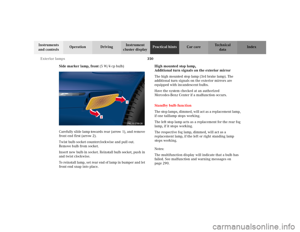
Side marker lamp, front (5 W/4 cp bulb)
Carefully slide lamp towards rear (arrow 1), and remove
front end first (arrow 2).
Twist bulb socket counterclockwise and pull out.
Remove bulb from socket.
Insert new bulb in socket. Reinstall bulb socket, push in
and twist clockwise.
To reinstall lamp, set rear end of lamp in bumper and let
front end snap into place.High mounted stop lamp,
Additional turn signals on the exterior mirror
The high mounted stop lamp (3rd brake lamp). The
additional turn signals on the exterior mirrors are
equipped with incandescent bulbs.
Have the system checked at an authorized
Mercedes-Benz Center if a malfunction occurs.
Standby bulb function
The stop lamps, dimmed, will act as a replacement lamp,
if one taillamp stops working.
The left stop lamp acts as a replacement for the rear fog
lamp, if it stops working.
The respective fog lamp, dimmed, will act as a
replacement lamp, if the left or right standing lamp
stops working.
Notes:
The multifunction display will indicate that a bulb has
failed. See malfunction and warning messages on
page 290.
2
1P82.10-2799-26