2002 MERCEDES-BENZ C CLASS COUPE light
[x] Cancel search: lightPage 217 of 399

214
Interior equipment
Te ch n i c a l
data
Instruments
and controls Operation
DrivingInstrument
cluster display Practical hints Car care Index
Parcel net in front passenger footwell
A small convenience parcel net is located in the front
passenger footwell. It is for small and light items, such
as road maps, mail, etc.
Wa r n i n g !
Do not place heavy or fragile objects, or objects
having sharp edges, in the parcel net.In an accident, during hard braking or sudden
maneuvers, they could be thrown around inside
the vehicle, and cause injury to vehicle occupants.
Page 226 of 399

223
Garage door opener
Te ch n i c a l
data
Instruments
and controls Operation
DrivingInstrument
cluster display Practical hints Car care Index
Rolling code programming:
To train a garage door opener (or other rolling code
devices) with the rolling code feature, follow these
instructions after completing the “Programming”
portion of this text. (A second person may make the
following training procedures quicker and easier.)
1. Locate training button on the garage door opener motor head unit. Exact location and color of the
button may vary by garage door opener brand. If
there is difficulty locating the transmitting button,
reference to garage door opener operator’s manual.
2. Press “training” button on the garage door opener motor head unit (which activates the “training
light”).
Note:
Following step 2, there are 30 seconds to initiate
step 3. 3. Firmly press and release the programmed
integrated remote control transmit button. Press
and release same button a second time to complete
the training process. (Some garage door openers
may required you to do this procedure a third time
to complete the training.)
4. Confirm the garage door operation by pressing the programmed button on the integrated remote
control transmitter.
Page 236 of 399

233
Tele Aid
Te ch n i c a l
data
Instruments
and controls Operation
DrivingInstrument
cluster display Practical hints Car care Index
Notes:
The indicator lamp in the Roadside Assistance
button
remains illuminated in red for approx.
10 seconds during the system self-check after turning
electronic key in starter switch to position 2 (together
with the “SOS” button and the Information
button ¡).
See system self-check on page 228 when the indicator
lamp does not light up in red or stays on longer than
approximately 10 seconds.
If the indicator lamp in the Roadside Assistance
button is illuminated continuously and there was
no voice connection to the Response Center established,
then the Tele Aid system could not initiate an Roadside
Assistance call (e.g. the relevant cellular phone network
is not available). The message “ROADSIDE
ASSISTANCE – CALL FAILED” appears in the
multifunction display.
Roadside Assistance calls can be terminated using the
ì button on the multifunction steering wheel. Information button ¡
Located below the center armrest cover is the
Information button
¡. Pressing and holding the
button (for longer than 2 seconds) will initiate a call to
the Customer Assistance Center. The button will flash
while the call is in progress. The message “INFO –
CONNECTING CALL” will appear in the multifunction
display. When the connection is established, the
message “INFO – CALL CONNECTED” appears in the
multifunction display. The Tele Aid system will transmit
data generating the vehicle identification number,
model, color and location (s ubject to availability of
cellular and GPS signals).
A voice connection between the Customer Assistance
Center representative and the occupants of the vehicle
will be established. When a voice connection is
established the audio system mutes and the message
“TELE AID – INFO CALL ACTIVE” appears in the
multifunction display. Information regarding the
operation of your vehicle, the nearest Mercedes-Benz
Center or Mercedes-Benz USA products and services is
ava i l ab le to yo u .
For more details concerning Tele Aid, please visit
www.mbusa.com and use your ID and password, sent to
you separately, to learn more (USA only).
Page 237 of 399

234
Tele Aid
Te ch n i c a l
data
Instruments
and controls Operation
DrivingInstrument
cluster display Practical hints Car care Index
Notes:
The indicator lamp in the Information button ¡
remains illuminated in red for approx. 10 seconds
during the system self-check after turning electronic
key in starter switch to position 2 (together with the
“SOS” button and the Roadside Assistance button ).
See system self-check on page 228 when the indicator
lamp does not light up in red or stays on longer than
approximately 10 seconds.
If the indicator lamp in the Information button ¡ is
illuminated continuously and there was no voice
connection to the Response Center established, then the
Tele Aid system could not initiate an Information call
(e.g. the relevant cellular phone network is not
available). The message “INFO – CALL FAILED” appears
in the multifunction display.
Information calls can be terminated using the
ì button on the multifunction steering wheel. Important!
If the indicator lamps do not start flashing after
pressing one of the buttons or remain illuminated (in
red) at any time, the Tele Aid system has detected a fault
or the service is not currently active, and may not
initiate a call.
Visit your Mercedes-Benz Center and have the system
checked or contact the Response Center at 1-800-756-
9018 (in the USA) or 1-888-923-8367 (in Canada) as
soon as possible.
Upgrade Signals
Tele Aid system processes calls using the following
priority.
• Automatic emergency – First priority
• Manual emergency – Second priority
• Roadside assistance – Third priority
• Information – Fourth priority
Should a higher priority call be initiated while you are
connected, an upgrade (altern ating) tone will be heard,
and the appropriate indicator lamp will flash. If certain
information such as vehicle identification number or
Customer information is not available, the operator may
Page 243 of 399

240
Starter switch
Te ch n i c a l
data
Instruments
and controls Operation
DrivingInstrument
cluster display Practical hints Car care Index
Starter switch
0 The electronic key can be withdrawn in this position
only. The steering is locked when the electronic key
is removed from the starter switch. If necessary,
move steering wheel slightly to allow the locking
mechanism to engage.
In vehicles with automatic transmission, the
electronic key can be removed only with the selector
lever in position “P”. After removing the electronic key or with the electronic key in starter switch
position 0 or 1 the selector lever is locked in
position “P”.
1 Most electrical consumers can be operated. For
detailed information see respective subjects.
2 Driving position.
Gear selector lever is unlocked.
To move the selector lever out of position “P” firmly
depress the service brake pedal.
3 Starting position.
See page 242 for instructions on starting and turning off
the engine.
Wa r n i n g !
When leaving the vehicle always remove the
electronic key from the starter switch, and lock the
vehicle. Do not leave children unattended in the
vehicle, or with access to an unlocked vehicle.
Unsupervised use of vehicle equipment may cause
serious personal injury.
Page 251 of 399

248
Automatic transmission
Te ch n i c a l
data
Instruments
and controls Operation
DrivingInstrument
cluster display Practical hints Car care Index
Stopping
For brief stops, e.g. at traffic lights, leave the
transmission in gear and hold vehicle with the service
brake.
For longer stops with the engine idling, shift into “N”
or “P” and hold the vehicle with the service brake.
When stopping the vehicle on an uphill gradient, do not
hold it with the accelerator, use the brake. This avoids
unnecessary transmission heat build up.
Maneuvering
To maneuver in tight areas, e.g. when pulling into a
parking space, control the vehicle speed by gradually
releasing the brakes. Accelerate gently and never
abruptly step on the accelerator.
To rock a vehicle out of soft ground (mud or snow),
alternately shift from forward to reverse, while applying
slight partial throttle. Rocking a vehicle free in this manner may cause the
ABS or traction system malfunction indicator lamp to
come on. Turn off and restart the engine to clear the
malfunction indication.
Wa r n i n g !
Getting out of your vehicle with the selector lever
not fully engaged in position “P” is dangerous.
Also, when parked on an incline, position “P” alone
may not prevent your vehicle from moving,
possibly hitting people or objects.Always set the parking brake in addition to shifting
to position “P”, see page 256 for parking brake. When parked on an incline, also turn front wheel
towards the road curb.When leaving the vehicle always remove the key
from the steering lock, and lock the vehicle. Do not
leave children unattended in the vehicle, or with
access to an unlocked vehicle. Children could move
the selector lever from position“P”, which could
result in an accident or serious injury.
Page 252 of 399

249
Automatic transmission
Te ch n i c a l
data
Instruments
and controls Operation
DrivingInstrument
cluster display Practical hints Car care Index
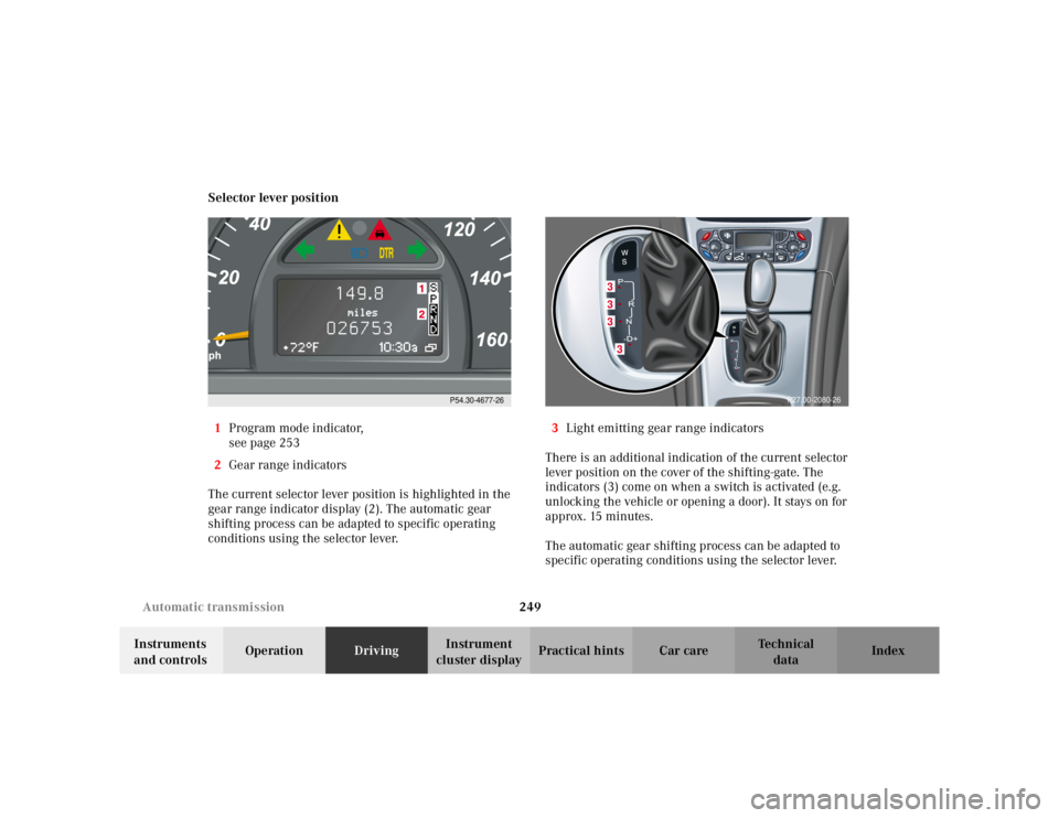
Selector lever position
1 Program mode indicator,
see page 253
2 Gear range indicators
The current selector lever position is highlighted in the
gear range indicator display (2). The automatic gear
shifting process can be adapted to specific operating
conditions using the selector lever. 3
Light emitting gear range indicators
There is an additional indication of the current selector
lever position on the cover of the shifting-gate. The
indicators (3) come on when a switch is activated (e.g.
unlocking the vehicle or opening a door). It stays on for
approx. 15 minutes.
The automatic gear shifting process can be adapted to
specific operating conditions using the selector lever.
P54.30-4677-26
3333
P27.00-2080-26
Page 254 of 399

251
Automatic transmission
Te ch n i c a l
data
Instruments
and controls Operation
DrivingInstrument
cluster display Practical hints Car care Index
Gear selection for special circumstances
The transmission gear ranges for special circumstances
can be selected by pressing the selector lever to the
right or the left with the selector lever in position “D”.
The gear range currently selected is highlighted in the
instrument cluster display.
Briefly press selector lever in the “D –” direction:
The transmission will shift from the current gear range
to the next lower gear range.
Press and hold selector lever in the “D –” direction:
The selector lever position display will switch to the
gear range currently selected by the automatic
transmission.
Shifting into another gear range that allows for quicker
acceleration or to slow the vehicle down is possible.
Downshifts can also be performed.
Note:
To avoid overrevving the engine when the selector lever
is moved in “D –” direction, the transmission will not
shift to a lower gear if the engine’s revolutions per
minute limit would be exceeded.
Briefly press selector lever in the “D +” direction:
The transmission will shift from the current gear range
to the next higher gear range. If the transmission is
already in gear range “D”, an additional upshift of one
gear is possible.
Press and hold selector lever in the “D +” direction:
The transmission will shift from the current gear
directly to gear range “D”.
Important!
With transmission in gear range “D”, “4” or “3”,
upshifting from 1st to 2nd to 3rd gear is delayed
depending on vehicle speed and engine temperature.
This allows the catalytic converter to heat up more
quickly to operating temperatures.
Wa r n i n g !
On slippery road surfaces, never downshift in order
to obtain braking action. This could result in drive
wheel slip and reduced vehicle control. Your
vehicle’s ABS will not prevent this type of loss of
control.