2002 MAZDA 6 fuel type
[x] Cancel search: fuel typePage 90 of 909

F1–2
OUTLINE
OUTLINE OF CONSTRUCTIONA6E390218881201•The fuel and emission control systems are essentially carried over from the current Mazda6 (GG), except for
the following features. (See Mazda6 Training Manual 3359-1*-02C.)
End Of Sie
FEATURESA6E390218881202System simplification
•Controller area network has been adopted with TCM communication (4WD).
TCM adoption
•DTC for CAN (TCM communication) has been adopted.
Modifications to match the vehicle characteristics
•The idle speed has been modified.
•Fuel pump (transfer) has been adopted.
End Of Sie
SPECIFICATIONSA6E390218881203
*1: Without the BARO sensor
*2: With the BARO sensor
Bold frames: New specifications
End Of Sie
OUTLINE
Item 2WD 4WD
Air cleaner element Type Paper element (oil permeated)
IAC valve Type Duty control
Fuel injectorType Hi-ohmic
Type of fuel delivery Top-feed
Type of drive Voltage
Pressure regulatorRegulating pressure
(kPa {kgf/cm
2, psi})440 {4.5, 64}
Fuel tankCapacity
(L {US qt, lmp qt})64 {68, 56} 62 {65, 54}
Fuel SpecificationUnleaded
(RON 90*
1/95*2 or above)Unleaded (RON 95 or above)
Catalyst Type TWC (monolythic)
EGR control Type Stepping motor type
Evaporative emission control
systemType Canister type
PCV system Type Closed type
Page 97 of 909

FUEL SYSTEM
F1–9
F1
End Of Sie
OUTLINEA6E391201006201•The fuel system is essentially carried over from that of the current Mazda6 (GG), except for the following. (See
Mazda6 Training Manual 3359-1*-02C.)
—A saddle type fuel tank has been adopted.
—A fuel pump (transfer) for fuel transmission has been added.
End Of Sie
STRUCTURAL VIEWA6E391201006202
.
End Of Sie
FUEL SYSTEM
7
5
4
3
6
1
2
A6E39122001
1 Fuel gauge sender sub-unit
2 Quick release connector (fuel tank side, transfer
hose part)
3 Non-return valve4 Quick release connector (fuel tank side, main fuel
pipe part)
5 Fuel tank
6 Fuel pump unit
7 Filler cap
Page 98 of 909

F1–10
FUEL SYSTEM
SYSTEM DIAGRAMA6E391201006203
.
End Of Sie
FUEL PUMP (TRANSFER)A6E391213350201Function
•The fuel tank for 4WD is saddle type. Fuel in the fuel gauge sender sub-unit side (right side) is pumped to the
left side of the fuel tank using the fuel pump (transfer).
Structure
•The fuel pump (transfer) is integrated into the fuel pump unit and it cannot be separately disassembled.
•The fuel pump (transfer) is composed of a relief valve and fuel jet pump.
87
5
4
3
6
1
2
:
9
10
A6E39122002
1 Filler cap
2 Pressure regulator
3 Fuel pump (transfer)
4 Fuel filter (high-pressure)
5Fuel pump6 Fuel filter (low-pressure)
7 Fuel pump unit
8 Pulsation damper
9 Fuel injector
10 Fuel flow
Page 100 of 909

F1–12
FUEL SYSTEM
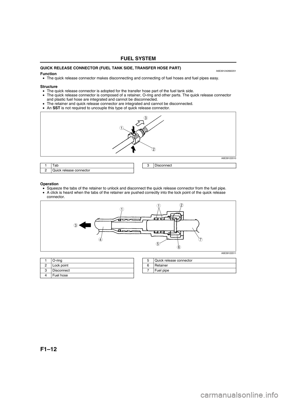
QUICK RELEASE CONNECTOR (FUEL TANK SIDE, TRANSFER HOSE PART)A6E391242692201Function
•The quick release connector makes disconnecting and connecting of fuel hoses and fuel pipes easy.
Structure
•The quick release connector is adopted for the transfer hose part of the fuel tank side.
•The quick release connector is composed of a retainer, O-ring and other parts. The quick release connector
and plastic fuel hose are integrated and cannot be disconnected.
•The retainer and quick release connector are integrated and cannot be disconnected.
•An SST is not required to uncouple this type of quick release connector.
.
Operation
•Squeeze the tabs of the retainer to unlock and disconnect the quick release connector from the fuel pipe.
•A click is heard when the tabs of the retainer are pushed correctly into the lock point of the quick release
connector.
.
End Of Sie
3
1
2
A6E39122010
1Tab
2 Quick release connector3 Disconnect
7
5
4
3
6
1
21
A6E39122011
1 O-ring
2 Lock point
3 Disconnect
4Fuel hose5 Quick release connector
6 Retainer
7 Fuel pipe
Page 109 of 909

CONTROL SYSTEM
F1–21
F1
CONTROLLER AREA NETWORK (CAN)A6E394018880205•PCM transmit/received the information in the CAN. For detail information of the CAN, see the “MULTIPLEX
COMMUNICATION SYSTEM.” (See T–3 OUTLINE.)
Transmit Information (4WD ATX Model)
•Engine control condition
•Torque reduction inhibit
•Engine speed
•Vehicle Speed
•TP
•Engine torque (without torque reduction)
•Engine torque (with torque reduction)
•Battery reconnection
•Engine loss torque
•ECT
•Travelled distance
•Fuel injection information
•MIL condition
•Generator warning light conditions
•Engine displacement
•Number of cylinders
•Air induction type
•Fuel type and delivery
•Country
•Transmission/axle type
•Tire circumference (front/rear)
Received Information (4WD ATX Model)
From ABS HU/CM, ABS/TCS HU/CM, or DSC HU/CM
•Wheel speed
—Front left, Front right, Rear left, and Rear right
•Travelled distance
•Brake system status
•Torque reduction request
•Brake system configuration
From TCM
•Desired torque
•Upper torque limit
•Turbineshaft speed
•Vehicle speed
•Torque reduction request
•Idle speed up request
•Racing select determination
•MIL indicate request
•Desired gear/selector lever position
•AT warning indicator light condition
•TCC condition
End Of Sie
Page 155 of 909

OUTLINE
F2–3
F2
OUTLINE OF CONSTRUCTIONA6E400218881201•The common rail injection system has been adopted for Mazda6 (GG, GY) MZR-CD (RF Turbo) engine
models.
•The fuel and emission control system is essentially carried over from that of the current MPV (LW) MZR-CD
(RF Turbo) engine models, except for the following features. (See MPV Workshop Manual Supplement 1737-
1*-02C.)
End Of Sie
FEATURESA6E400218881202Improved Emission Performance
•Warm up oxidation catalytic converter capacity has been increased.
System Simplification
•Immobilizer unit has been equipped into PCM
•Cruise control system has been adopted.
•Electrical fan control has been changed.
•CAN has been changed.
Improved Serviceability
•DTCs, PID monitoring items, and simulation test items have been changed.
•KOEO/KOER self-test items have been changed.
End Of Sie
SPECIFICATIONSA6E400218881203
Bold frames: New specifications
End Of Sie
OUTLINE
ItemNew Mazda6 (GG, GY) Current MPV (LW)
MZR-CD (RF Turbo)
Air cleaner element Type Non woven fabric (dry)
Supercharger Type Turbocharger
Glow plug Type Metal
Pump Type Supply pump
Fuel tankCapacity
64 {16.9, 14.1} 75 {19.8, 16.5}
(L {US gal, lmp gal})
Catalyst Type Warm up oxidation catalyst, Oxidation catalyst
EGR control Type Duty control
PCV system Type Closed
Page 176 of 909

F2–24
CONTROL SYSTEM, ON-BOARD DIAGNOSTIC
CONTROLLER AREA NETWORK (CAN)A6E404018881206Outline
•The PCM transmit/received the information other units using CAN to simplify the system.
Transmit Information
•Engine speed
•Vehicle speed
•Accelerator pedal position
•Fuel injection information
•Torque reduction inhibit
•Intake air temperature
•Engine coolant temperature
•Travelled distance
•Glow indicator light conditions
•Engine displacement
•Number of cylinders
•Air induction type
•Fuel type and delivery
•Country
•Transmission/axle type
•Tire circumference (front/rear)
•Cruise main indicator light conditions
•Cruise set indicator light conditions
Received Information
•Torque reduction request from DSC HU/CM
•Wheel speed from ABS HU/CM or DSC HU/CM
—Front left
—Front right
•Travelled distance from ABS HU/CM or DSC HU/CM
End Of Sie
OUTLINEA6E407018881201•The on-board diagnostic system is essentially carried over from that of the current MPV (LW) MZR-CD (RF
Turbo) engine models, except for the following. (See MPV Workshop Manual Supplement 1737-1*-02C.)
—DTCs, PID monitoring items, and simulation items have been changed.
—KOEO/KOER self-test items have been changed.
End Of Sie
DTCA6E407018881202
×: Applicable –: Not applicable
ON-BOARD DIAGNOSTIC
DTC Condition Detection condition MILMemory
function
P0016Crankshaft position-camshaft position
correlation malfunctionInput signals from CKP sensor and CMP sensor
are misaligned.××
P0088 Fuel pressure system too highFuel pressure is higher than preprogrammed
criteria.–×
P0091 Suction control valve circuit low inputInput voltage from suction control valve does not
change from off to on.××
P0092 Suction control valve circuit high inputInput voltage from suction control valve does not
change from on to off.××
P0093 Fuel system leak detectionFuel pressure after fuel injection is lower than
preprogrammed criteria.××
P0097 IAT sensor No.1 circuit low input Input voltage from IAT sensor No.1 is below 0.1 V.××
P0098 IAT sensor No.1 circuit high input Input voltage from IAT sensor No.1 is above 5.0 V.××
P0102 MAF sensor circuit low input Input voltage from MAF sensor is below 0.2 V.××
P0103 MAF sensor circuit high input Input voltage from MAF sensor is above 4.9 V.××
P0107 Boost sensor circuit low inputInput voltage from boost sensor is below 1.9 V
when engine speed is 2,400 rpm or above and
accelerator opening angle is 50% or above.××
P0108 Boost sensor circuit high input Input voltage from boost sensor is above 4.9 V.××
Page 419 of 909

K2–4
AUTOMATIC TRANSAXLE
Bold frames:New specifications
End Of Sie
OUTLINEA6E571401030201•Adopted new JA5AX-EL automatic transaxle.
•Newly designed FF type five-speed automatic transaxle.
—Use of 3 sets of planetary gears, and a wider gear ratio setting realizes improvement of acceleration-from-
standing-start performance, fuel economy, and quietness. Also, by placement of two sets of planetary gears
in parallel with one set, the automatic transaxle is more compact.
•Adopted 2-4 brake clutch.
—Adopted a wet-type, multi-plate 2-4 brake clutch instead of the 2-4 brake band used in the past, for
smoother gear switching performance.
•Adopted centrifugal balance clutch
—The newly adopted centrifugal balance clutch pushes the clutch piston forcefully to low and high clutch by
centrifugal hydraulic pressure for smoother gear switching with batter response.
•Adopted controller area network (CAN)
—By adopting CAN, The TCM is always in contact with other computers in the car and controls the automatic
transaxle properly. This has also made troubleshooting diagnosis easier for the entire vehicle.
•Solenoid, sensor
—Adoption of four duty-type solenoids, five ON-OFF type solenoids, and three revolving sensors realizes
finer, more expedient control of gear shifting performance.
•Adoption of revers inhibit control
—If the reverse position is selected by mistake while driving in forward motion, the reverse inhibit control
system will cancel the operation electronically and set the position to neutral as a safety enhancement.
Outline of Operation
•The operation of the electronic automatic transaxle is classified into three systems: the electronic control
system, the hydraulic pressure control system, and the powertrain system (includes the torque converter
system.)
Electronic control system
•According to the signals from the switches and sensors in the input system, the TCM outputs the signal
which matches the present driving condition to the ON/OFF type solenoids and the duty-cycle type
solenoids in the hydraulic pressure control system.
Hydraulic pressure control system
•According to the signals from the TCM, each solenoid operates to switch the hydraulic passages in the
control valve body and controls the clutch engagement pressure.
•The line pressure is adjusted by the duty-cycle type pressure control solenoid. The hydraulic passages
are switched by the ON/OFF type solenoids and the clutch engagement pressure is controlled by the
duty-cycle type solenoids.
Powertrain system
•The driving force from the engine is transmitted through the torque converter to the transaxle.
•The transmitted driving force operates each clutch and brake according to the clutch engagement
pressure from the duty-cycle type solenoid, and the planetary gears change the gear ratio to the
optimal driving force. The changed driving force is transmitted through the differential to the axle shaft
and then the tires.
AUTOMATIC TRANSAXLE