Page 63 of 909

B2–32
ENGINE
No.1 Engine Mount Bracket Installation Note
1. Tighten No.1 engine mount bracket bolt A.
Tightening torque
93.1—116.6 N·m {9.5—11.8 kgf·m,
68.7—85.9 ft·lbf}
2. Tighten No.1 engine mount bracket bolt B.
Tightening torque
93.1—116.6 N·m {9.5—11.8 kgf·m,
68.7—85.9 ft·lbf}
No.1 Engine Mount Rubber Installation Note
1. Tighten through-bolt A on the No.1 engine mount
bracket.
Tightening torque
85.3—116.6 N·m {8.7—11.8 kgf·m,
62.9—85.9 ft·lbf}
2. Tighten through-bolt B on the front crossmember
side.
Tightening torque
93.1—116.6 N·m {9.5—11.8 kgf·m,
68.7—85.9 ft·lbf}
End Of SieENGINE DISASSEMBLY/ASSEMBLYA6E2324010012021. Disconnect the engine and transaxle. (See J2–7 MANUAL TRANSAXLE REMOVAL/INSTALLATION.)
2. Remove the intake-air system. (See F2–36 INTAKE-AIR SYSTEM REMOVAL/INSTALLATION.)
3. Remove the exhaust system. (See F2–57 EXHAUST SYSTEM REMOVAL/INSTALLATION.)
4. Remove the generator. (See G–7 GENERATOR REMOVAL/INSTALLATION.)
5. Remove the clutch. (See H–5 CLUTCH UNIT REMOVAL/INSTALLATION (A65M-R manual transaxle
models).)
6. Remove the vacuum pump. (See P–13 VACUUM PUMP REMOVAL/INSTALLATION (MZR-CD (RF
TURBO)).)
7. Remove the P/S oil pump. (See N–16 POWER STEERING OIL PUMP (MZR-CD (RF Turbo)) REMOVAL/
INSTALLATION.)
8. Disassemble in the order indicated in the table.
9. Assemble in the reverse order of disassembly.
A
B
A6E2324W207
A B
A6E2324W201
Page 64 of 909
ENGINE
B2–33
B2
.
A/C Compressor Bracket Installation Note
1. Tighten the A/C compressor bracket bolts in the
order shown.
Tightening torque
38—51 N·m {3.8—5.3 kgf·m, 28—38 ft·lbf}
End Of Sie
N·m { kgf·m, ft·lbf} 38—51
{3.8—5.3, 28—38}
1
2
A6E2324W105
1 A/C compressor bracket
(See B2–33 A/C Compressor Bracket Installation
Note)2 Seal plate
43
1
2
A6E2324W106
Page 71 of 909

OIL PRESSURE INSPECTION
D–7
D
OIL PRESSURE INSPECTIONA6E331001003201MZR-CD (RF Turbo)
Warning
•Continuous exposure to USED engine oil has caused skin cancer in laboratory mice. Protect your
skin by washing with soap and water immediately after working with engine oil.
•Hot engines and engine oil can cause severe burns. Turn off the engine and wait until it and the
engine oil have cooled.
1. Disconnect the negative battery cable.
2. Remove the under cover.
3. Remove the oil pressure switch.
4. Screw the SST into the oil pressure switch
installation hole.
5. Warm up the engine to normal operating
temperature.
6. Run the engine at the specified speed, and note
the gauge readings.
•If the pressure is not as specified, inspect for
the cause and repair or replace if necessary.
Oil pressure (approximate quantity) [oil
temperature: 100°C {212°F}]
147 kPa {1.5 kgf/cm
2, 21psi} min [1,000 rpm]
343 kPa {3.5 kgf/cm2, 50 psi} min [3,000 rpm]
Note
•The oil pressure can vary with oil viscosity and temperature.
7. Stop the engine and wait until it is cool.
8. Remove the SST.
Caution
•Any sealant stuck at the end of the oil pressure switch can cause operation malfunction of the oil
pressure switch.
Be sure there is no sealant at the end of the oil pressure switch.
9. Apply silicone sealant to the oil pressure switch
threads as shown.
10. Install the oil pressure switch.
Tightening torque
12—17 N·m {1.2—1.8 kgf·m, 9—13 ft·lbf}
11. Install the intake manifold bracket.
12. Start the engine and inspect for oil leakage.
•If the oil leaks, specify the faulty part and
repair or replace it.
13. Install the under cover.
End Of Sie
OIL PRESSURE INSPECTION
49 0187 280A
A6E3310W100
1.0—2.0 {0.04—0.07}
4.0—6.0 {0.16—0.23}
mm {in}
SEALANTSEALANT
A6E3310W101
Page 72 of 909

D–8
ENGINE OIL
ENGINE OIL INSPECTIONA6E331214001201MZR-CD (RF Turbo)
1. Position the vehicle on level ground.
2. Warm up the engine to normal operating temperature.
3. Stop the engine and wait for 5 min.
4. Verify that the oil level is between the L and F marks on the dipstick and check the engine oil condition.
•If the oil level is below the L mark, add engine oil. (See D–8 ENGINE OIL REPLACEMENT.)
End Of SieENGINE OIL REPLACEMENTA6E331214001202MZR-CD (RF Turbo)
Warning
•Hot engines and engine oil can cause severe burns. Turn off the engine and wait until it and the
engine oil have cooled.
•A vehicle that is lifted but not securely supported on safety stands is dangerous. It can slip or fall,
causing death or serious injury. Never work around or under a lifted vehicle if it is not securely
supported on safety stands.
•Continuous exposure to USED engine oil has caused skin cancer in laboratory mice. Protect your
skin by washing with soap and water immediately after working with engine oil.
Caution
•In case you spill engine oil on the front pipe, wipe it off completely. If you fail to wipe the spilled
oil, it will produce fumes because of the heat.
1. Position the vehicle on level ground.
2. Remove the the oil filler cap.
3. Remove the under cover.
4. Remove the oil pan drain plug.
5. Drain the engine oil into a container.
6. Install the oil pan drain plug with a new the washer.
Tightening torque
12—17 N·m {1.2—1.8 kgf·m, 9—13 ft·lbf}
Note
•The amount of residual oil in the engine can vary with the replacement method, oil temperature, etc. Verify
the oil level after engine oil replacement.
7. Refill the engine oil with the specified type and amount, then install the oil filler cap.
Oil capacity (approximate quantity)
L {US qt, Imp qt}
Note
•The maintenance intervals on scheduled maintenance table (See GI–8 SCHEDULED MAINTENANCE
TABLE) can only be supported with the use of following oils.
Recommended Engine Oil
8. Start the engine and inspect for oil leakage.
•If the oil leaks, specify the faulty part and repair or replace it.
9. Inspect the oil level .
•If the necessary, add oil. (See D–8 ENGINE OIL INSPECTION.)
10. Install the under cover.
End Of Sie
ENGINE OIL
Item Specification
Total (dry engine) 5.5 {5.8, 4.8}
Oil replacement 4.8 {5.1, 4.2}
Oil and oil filter replacement 5.0 {5.3, 4.4}
Item Specification
Engine oil GradeAPI CF CD, CE, CF-4
ACEA B1 or B3 B3 B3 or B4
Viscosity (SAE) 5W-30 10W-40 5W-30, 10W-30
RemarksMazda genuine Dexelia oil e.g. —
Page 75 of 909
OIL PAN
D–11
D
3. Screw an oil pan bolt into the weldnut to make a
small gap between the cylinder block and the oil
pan.
4. Remove the oil pan using the separator tool.
Oil Pan Installation Note
Caution
•If the bolts are reused, remove the old sealant from the bolt threads. Tightening a bolt that has old
sealant on it can cause bolt hole damage.
1. Apply silicone sealant to the oil pan along the
inside of the bolt holes and overlap the ends.
Thickness
2.5—3.5 mm {0.099—0.137 in}
2. Install the oil pan.
3. Hand tighten the flangeless bolts and tighten the
flanged bolts
Tightening torque
7.9—10.7 N·m
{80—110 kgf·cm, 69.5—95.4 in·lbf}
End Of Sie
WELD NUT
A6E3320W101
A6E3320W102
OLD SEALANTCRACKS
A6E3320W103
SEALANTSEALANT
A6E3320W104
Page 109 of 909

CONTROL SYSTEM
F1–21
F1
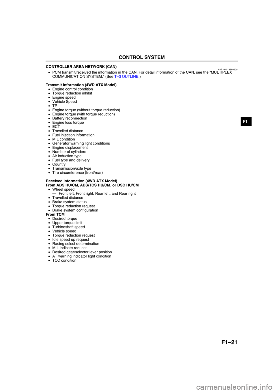
CONTROLLER AREA NETWORK (CAN)A6E394018880205•PCM transmit/received the information in the CAN. For detail information of the CAN, see the “MULTIPLEX
COMMUNICATION SYSTEM.” (See T–3 OUTLINE.)
Transmit Information (4WD ATX Model)
•Engine control condition
•Torque reduction inhibit
•Engine speed
•Vehicle Speed
•TP
•Engine torque (without torque reduction)
•Engine torque (with torque reduction)
•Battery reconnection
•Engine loss torque
•ECT
•Travelled distance
•Fuel injection information
•MIL condition
•Generator warning light conditions
•Engine displacement
•Number of cylinders
•Air induction type
•Fuel type and delivery
•Country
•Transmission/axle type
•Tire circumference (front/rear)
Received Information (4WD ATX Model)
From ABS HU/CM, ABS/TCS HU/CM, or DSC HU/CM
•Wheel speed
—Front left, Front right, Rear left, and Rear right
•Travelled distance
•Brake system status
•Torque reduction request
•Brake system configuration
From TCM
•Desired torque
•Upper torque limit
•Turbineshaft speed
•Vehicle speed
•Torque reduction request
•Idle speed up request
•Racing select determination
•MIL indicate request
•Desired gear/selector lever position
•AT warning indicator light condition
•TCC condition
End Of Sie
Page 116 of 909

F1–28
FUEL SYSTEM
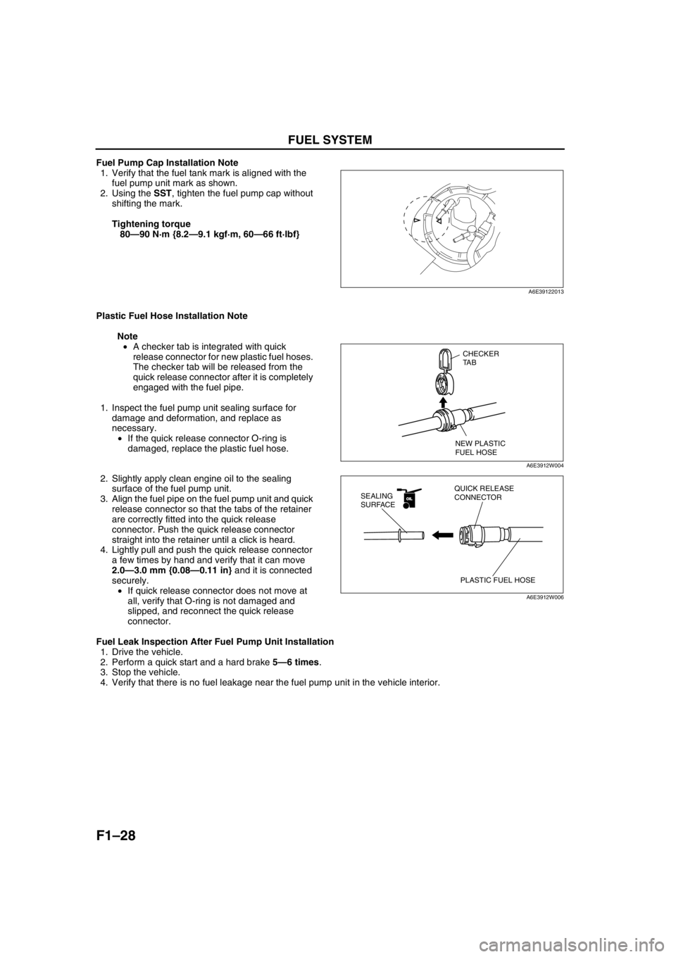
Fuel Pump Cap Installation Note
1. Verify that the fuel tank mark is aligned with the
fuel pump unit mark as shown.
2. Using the SST, tighten the fuel pump cap without
shifting the mark.
Tightening torque
80—90 N·m {8.2—9.1 kgf·m, 60—66 ft·lbf}
Plastic Fuel Hose Installation Note
Note
•A checker tab is integrated with quick
release connector for new plastic fuel hoses.
The checker tab will be released from the
quick release connector after it is completely
engaged with the fuel pipe.
1. Inspect the fuel pump unit sealing surface for
damage and deformation, and replace as
necessary.
•If the quick release connector O-ring is
damaged, replace the plastic fuel hose.
2. Slightly apply clean engine oil to the sealing
surface of the fuel pump unit.
3. Align the fuel pipe on the fuel pump unit and quick
release connector so that the tabs of the retainer
are correctly fitted into the quick release
connector. Push the quick release connector
straight into the retainer until a click is heard.
4. Lightly pull and push the quick release connector
a few times by hand and verify that it can move
2.0—3.0 mm {0.08—0.11 in} and it is connected
securely.
•If quick release connector does not move at
all, verify that O-ring is not damaged and
slipped, and reconnect the quick release
connector.
Fuel Leak Inspection After Fuel Pump Unit Installation
1. Drive the vehicle.
2. Perform a quick start and a hard brake 5—6 times.
3. Stop the vehicle.
4. Verify that there is no fuel leakage near the fuel pump unit in the vehicle interior.
End Of Sie
A6E39122013
CHECKER
TA B
NEW PLASTIC
FUEL HOSE
A6E3912W004
OILOIL
PLASTIC FUEL HOSE QUICK RELEASE
CONNECTOR SEALING
SURFACE
A6E3912W006
Page 120 of 909
F1–32
EXHAUST SYSTEM
Exhaust Manifold Installation Note
1. Tighten the exhaust manifold installation nuts in
the order shown.
Bracket Installation Note
1. Temporarily tighten the bracket installation bolt by the side of the exhaust manifold.
2. Verify that there is 2.0—4.0 mm {0.08—0.15 in}
gap between the exhaust manifold and the
bracket.
3. Tighten the bracket installation bolt by the side of
the cylinder block.
Tightening torque
37.3—52.0 N·m {3.81—5.30 kgf·m, 27.6—38.3
ft·lbf}
4. Tighten the bracket installation bolt by the side of
the exhaust manifold.
Tightening torque
40—55 N·m {4.1—5.6 kgf·m, 30—40 ft·lbf}
Exhaust Manifold Insulator (Upper) Installation Note
1. Tighten the exhaust manifold insulator (upper)
installation bolts in the order shown.
End Of Sie
75
4
3
1
2
6
A6J3914W003
2.0—4.0 {0.08—0.15}
mm {in}EXHAUST MANIFOLDBRACKET
A6E39142003
5
4
3
12
A6E39142006