Page 406 of 909

J2–4
MANUAL TRANSAXLE
TRANSAXLE OIL INSPECTIONA6E5212270012011. Park the vehicle on level ground.
2. Remove the filler plug and gasket.
3. Verify that the oil is near the brim of the plug port.
•If the oil level is low, add the specified amount
and type of oil through the filler plug hole.
Specified oil grade
API Service GL-4 or GL-5
Specified oil viscosity
SAE 75W-90
4. Install a new gasket and the filler plug.
Tightening torque
30.0—39.0 N·m
{3.06—3.98 kgf·m, 22.1—28.8 in·lbf}
End Of Sie
TRANSAXLE OIL REPLACEMENTA6E5212270012021. Remove the drain plug with the gasket.
2. Drain the oil into a suitable container.
3. Install a new gasket and the drain plug.
Tightening torque
30.0—39.0 N·m
{3.06—3.98 kgf·m, 22.1—28.8 in·lbf}
4. Remove the filler plug with gasket and add the
specified amount and type of oil through the filler
plug hole until the level reaches the bottom of the
filler plug hole.
Specified oil grade
API Service GL-4 or GL-5
Specified oil viscosity
SAE 75W-90
Capacity (approximate quantity)
2.30 L {2.40 US qt, 2.00 lmp qt}
5. Install a new gasket and the filler plug.
Tightening torque
30.0—39.0 N·m
{3.06—3.98 kgf·m, 22.1—28.8 in·lbf}
End Of Sie
MANUAL TRANSAXLE
DRAIN PLUG FILLER PLUG
A6E5212W010
DRAIN PLUG FILLER PLUG
A6E5212W010
Page 407 of 909

MANUAL TRANSAXLE
J2–5
J2
OIL SEAL (DIFFERENTIAL) REPLACEMENTA6E5212192402011. On level ground, jack up the vehicle and support it evenly on safety stands.
2. Drain the oil from the transaxle.
3. Remove the front wheels and splash shields.
4. Separate the drive shaft and joint shaft from the transaxle. (See Section M.)
5. Remove the oil seals using a screwdriver.
6. Using the SSTs and a hammer, tap each new oil
seal in evenly until the SSTs contact the transaxle
case.
7. Coat the lip of each oil seal with transaxle oil.
8. Insert the drive shaft and joint shaft into the
transaxle. (See Section M.)
9. Install the wheels and splash shields.
10. Add the specified amount and type of oil. (See
J2–4 TRANSAXLE OIL REPLACEMENT.)
End Of SieREVERSE SWITCH INSPECTIONA6E5212190102011. Disconnect the reverse switch connector.
2. Shift the shift lever to each position, and inspect
for continuity between terminals A and B.
•If not as specified, replace the reverse switch.
(See J2–6 REVERSE SWITCH REMOVAL/
INSTALLATION.)
3. Connect the reverse switch connector.
End Of Sie
AME5212W005
49 G030 797
49 U027 003
A6E5212W011
REVERSE SWITCH
A6E5212W012
BA REVERSE SWITCH
PART SIDE CONNENTOR
A6E5212W013
Shift positionConnector terminal
AB:
Continuity
Reverse
Others
A6E5212W014
Page 418 of 909

OUTLINE
K2–3
K2
FEATURESA6E570201030201ATX
Improved marketability
•New JA5AX-EL automatic transaxle for 4WD is used with on L3 engine.
Improved shift quality
•Five speed automatic transaxle has been adopted.
•The feedback control system has been adopted.
•The centrifugal balance clutch chambers have been adopted.
•A plate-type clutch pack replaces the band brake in the 2-4 brake.
High efficiency, compactness, and light weight
•Miniature trochoid gear type oil pump with torque converter direct drive has been adopted.
End Of Sie
SPECIFICATIONSA6E570201030202
OUTLINE
ItemNew Mazda6 (GY) Current MPV (LW)
–For General
(R.H.D.)
specs.Except for
General
(R.H.D.)
specs.
Transaxle type JA5AX-EL JA5A-EL
Gear ratio1GR 3.801
2GR 2.131
3GR 1.364
4GR 0.935
5GR (O/D) 0.685
Reverse 2.970
Final gear ratio 3.491 3.290 3.491
ATFType
ATF M-III or equivalent (e.g. Dexron
®III)
Capacity (approximate quantity)
(L {US qt, Imp qt})8.3 {8.8, 7.3} 9.7 {10.3, 8.5}
Torque converter stall torque ratio 1.86:1
Hydraulic system (Number of
drive/driven plates)Low clutch 6/6 7/7
2-4 brake 3/4
High clutch 5/5
Direct clutch 3/5 4/4
Reverse clutch 2/2
Low and reverse brake 6/5
Band servo (mm {in})Reduction accumulator piston outer
dia./reduction band servo piston
outer dia.49.66/57.64
Number of front planetary gear
teethRing gear 74
Sun gear 34
Pinion gear 20
Number of rear planetary gear
teethRing gear 75
Sun gear 42
Pinion gear 17
Number of reduction planetary
gear teethRing gear 85
Sun gear 31
Pinion gear 27
Number of output gear teeth 41
Number of idler gear teeth 47
Number of reduction gear teeth 22 23 22
Number of ring gear teeth 67 66 67
Transfer oilTypeSAE 80W-90
API Service GL-5–
Capacity (approximate quantity)
(L {US qt, Imp qt})0.62 {0.66, 0.55}–
Page 456 of 909
AUTOMATIC TRANSAXLE
K2–41
K2
OIL PUMP DESCRIPTIONA6E571419220201Outline
•The light-weight, compact, and quiet trochoid type oil pump reduces pump driving torque.
•The direct drive type oil pump is placed behind the torque converter.
Structure/Operation
•The outer rotor and inner rotor are installed in the oil pump housing.
•The inner rotor in the oil pump housing is driven by the torque converter.
•When the inner rotor in the oil pump rotates, the ATF is drawn to the oil pump. The discharge amount is
proportional to the rotating speed of the torque converter.
End Of Sie
AMU0517S015
AMU0517S016
Page 458 of 909

AUTOMATIC TRANSAXLE
K2–43
K2
When the clutch pressure is not applied
•When the clutch drum rotates, centrifugal force acts on the residual ATF in the clutch chamber to push against
the piston. However, centrifugal force also acts on the ATF filled in the centrifugal balance clutch chamber to
push back the piston. As a result, the two forces are eliminated and the piston remains stationary, thus
preventing clutch engagement.
When the clutch pressure is applied
•When clutch pressure is applied to the clutch chamber, the clutch pressure overcomes the oil pressure and the
spring force in the opposite centrifugal balance clutch chamber, and pushes the piston to engage the clutches.
Because the centrifugal force acting on the clutch pressure in the clutch chamber is canceled by another
centrifugal force acting on the ATF filled in the centrifugal balance clutch chamber, the influence of the
centrifugal force created by the clutch drum revolution speed is eliminated. As a result, stable piston pushing
force is obtained in all rotation ranges, and smoother shifts can be made.
End Of SieCONTROL VALVE BODY DESCRIPTIONA6E571421100201Outline
•The control valve body is composed of four bodies: the sub lower body, lower body, internal body, and the upper
body.
•To minimize the component in the control valve body, clutch engagement is electronically controlled, hydraulic
circuits were simplified and the valve types reduced.
AMU0517S019
Page 464 of 909
AUTOMATIC TRANSAXLE
K2–49
K2
ON/OFF type (two-way)
Normal low
•De-energized (OFF)
—The TCM does not apply an electric current to the solenoid valves. The rod moves upward by hydraulic
pressure and the drain port opens.
•Energized (ON)
—The TCM applies an electric current to the solenoid valves. This excites the coil and forces the rod to move
downward to retain hydraulic pressure.
End Of Sie
AMU0517S027
Page 494 of 909

AUTOMATIC TRANSAXLE
K2–79
K2
Automatic Transaxle Fluid (ATF) Level Inspection
Caution
•The ATF amount varies according to ATF's temperature. Therefore, when checking the ATF level or
replacing the ATF, use a thermometer to measure the temperature then adjust the ATF amount to
the specified level according to the specified temperature.
1. Park the vehicle on level ground.
2. Apply the parking brake and position wheel chocks securely to prevent the vehicle from rolling.
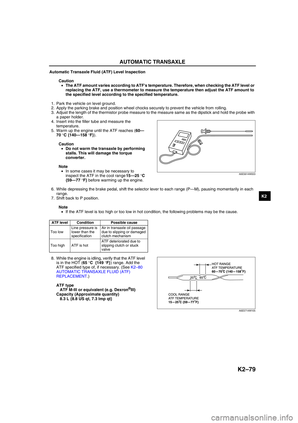
3. Adjust the length of the thermistor probe measure to the measure same as the dipstick and hold the probe with
a paper holder.
4. Insert into the filler tube and measure the
temperature.
5. Warm up the engine until the ATF reaches (60—
70 °C {140—158 °F}).
Caution
•Do not warm the transaxle by performing
stalls. This will damage the torque
converter.
Note
•In some cases it may be necessary to
inspect the ATF in the cool range 15—25 °C
{59—77 °F} before warming up the engine.
6. While depressing the brake pedal, shift the selector lever to each range (P—M), pausing momentarily in each
range.
7. Shift back to P position.
Note
•If the ATF level is too high or too low in hot condition, the following problems may be the cause.
8. While the engine is idling, verify that the ATF level
is in the HOT (65 °C {149 °F}) range. Add the
ATF specified type of, if necessary. (See K2–80
AUTOMATIC TRANSAXLE FLUID (ATF)
REPLACEMENT.)
ATF type
ATF M-III or equivalent (e.g. Dexron
®III)
Capacity (Approximate quantity)
8.3 L {8.8 US qt, 7.3 Imp qt}
End Of Sie
ATF level Condition Possible cause
Too lowLine pressure is
lower than the
specificationAir in transaxle oil passage
due to slipping or damaged
clutch mechanism
Too high ATF is hotATF deteriorated due to
slipping clutch or stuck
valve
A6E5614W003
A6E5714W105
Page 495 of 909

K2–80
AUTOMATIC TRANSAXLE
AUTOMATIC TRANSAXLE FLUID (ATF) REPLACEMENTA6E571419001202
Warning
•When the transaxle and ATF are hot, they can badly burn you. Turn off the engine and wait until
they are cool before changing the ATF.
1. Remove the oil dipstick.
2. Remove the oil drain plug and washer.
3. Drain the ATF into a container.
4. Install a new washer and the drain plug.
Tightening torque
39—54 N·m {3.9—5.6 kgf·m, 29—40 ft·lbf}
5. Add the specified type of ATF through the oil filler
tube, until ATF level reaches lower notch of
dipstick.
ATF type
ATF M-III or equivalent (e.g. Dexron
®III)
Capacity (Approximate quantity)
8.3 L {8.8 US qt, 7.3 Imp qt}
6. Verify that the ATF level is in the HOT (65 °C {149 °F}) range.
•Add ATF to the specified level as necessary.
End Of Sie
TRANSAXLE RANGE (TR) SWITCH INSPECTIONA6E571419440201
Note
•Input signals of the TR switch can be inspected with a WDS or equivalent. (See K2–90 TCM
INSPECTION.)
Inspection of Operation
1. Verify that the starter operates only with the ignition switch at the START position and the selector lever in P
and N positions.
•If not as specified, inspect for continuity at the TR switch. (See K2–80 Inspection of Continuity.)
2. Verify that the back-up lights illuminate when shifted to R position with the ignition switch at the ON position.
•If not as specified, inspect for continuity at the TR switch.
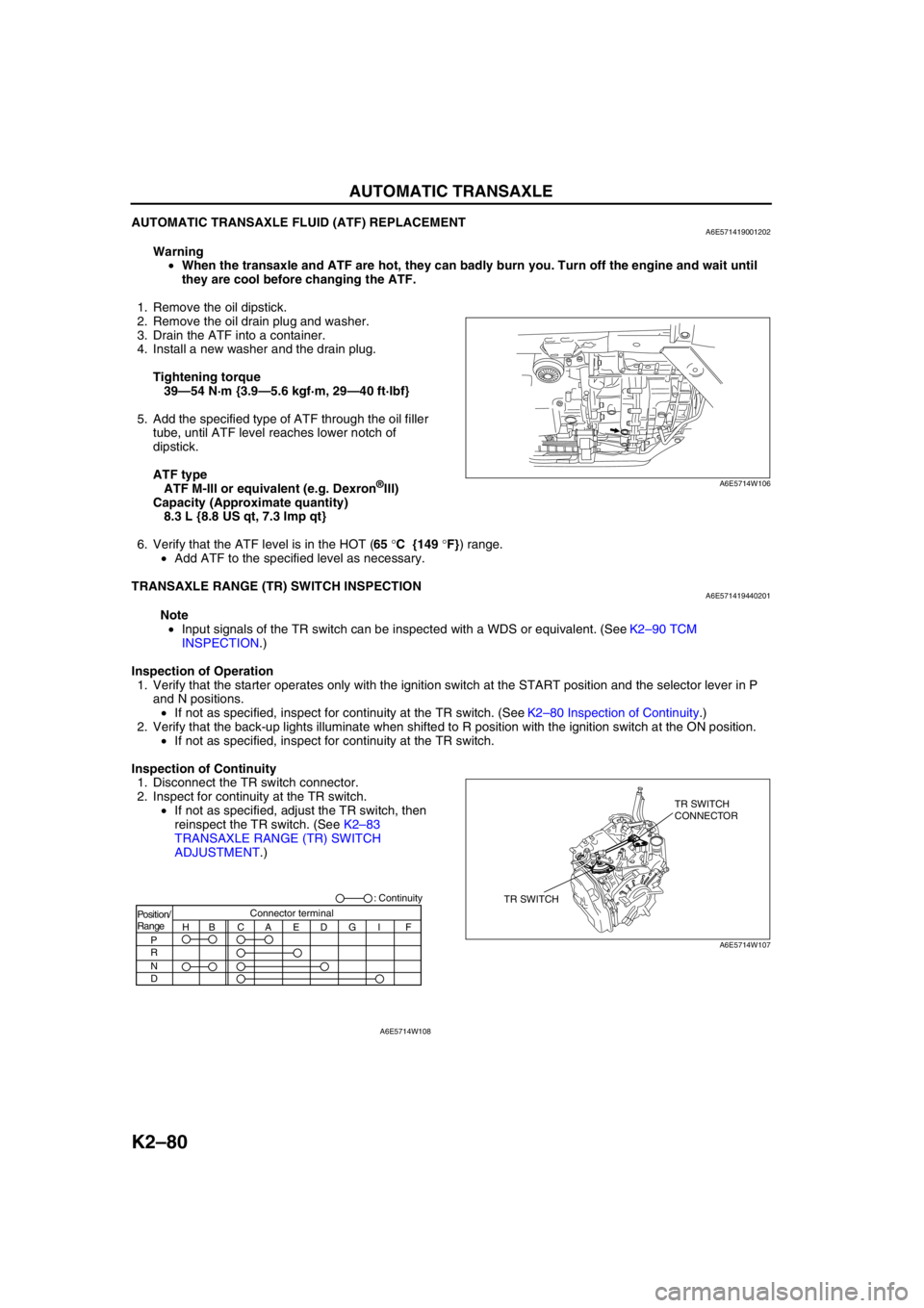
Inspection of Continuity
1. Disconnect the TR switch connector.
2. Inspect for continuity at the TR switch.
•If not as specified, adjust the TR switch, then
reinspect the TR switch. (See K2–83
TRANSAXLE RANGE (TR) SWITCH
ADJUSTMENT.)
A6E5714W106
TR SWITCHTR SWITCH
CONNECTOR
A6E5714W107
Position/
Range
H
P
R
N
DBCAEDGI FConnector terminal: Continuity
A6E5714W108