Page 429 of 909
K2–14
AUTOMATIC TRANSAXLE
CAN
signalThrottle
position
signalXX XXXXXX
Engine
torque
signal
(without
torque
down)XXXXXX
Engine
torque
signal
(with
torque
down)XXXXX
Engine
torque
signal
(loss
torque)XXXXXX
Engine
coolant
temperatu
re signalXX
Engine
speed
signalX XXX XX
Torque
reduce
signalXXXXX
Battery
OFF
signalXX
Output
ON/
OFF
typeShift
solenoid
AXX X
Shift
solenoid
BXX X
Shift
solenoid
CXX X
Reduction
timing
solenoid
valveXX X
Neutral
shift
solenoid
valveXXXX X ComponentControl item
Shift
controlLine
pressure
controlReverse
inhibition
controlShift
transient
controlFeedbac
k controlTCC
controlN-D
select
controlSlope
mode
controlOBD
system
Page 430 of 909
AUTOMATIC TRANSAXLE
K2–15
K2
X : Available
End Of SiePOWERTRAIN DESCRIPTIONA6E571401030207Outline
•In the powertrain system, the hydraulic pressure transported by the control valve operates the clutch, and
brake, and the planetary gear changes the gear ratio according to the driving conditions.
Structure
•The powertrain system consists of seven pairs of clutches, brake, brake band, two pairs of one-way clutches,
and simple type planetary gears.
Duty
typePressure
control
solenoidXX XX X
2-4 brake
solenoid
valveXX XX X
High
clutch
solenoid
valveXX XX X
TCC
solenoid
valveXXX
CAN
signalReduce
torque
signalXXX
Range
signalX
Turbine
speed
signalX
ATF
temperatu
re signalX
TCC
signalXX
Racing
select
signalX
MIL
indicate
request
signalX
AT
warning
light
request
signalX ComponentControl item
Shift
controlLine
pressure
controlReverse
inhibition
controlShift
transient
controlFeedbac
k controlTCC
controlN-D
select
controlSlope
mode
controlOBD
system
Page 479 of 909
K2–64
AUTOMATIC TRANSAXLE
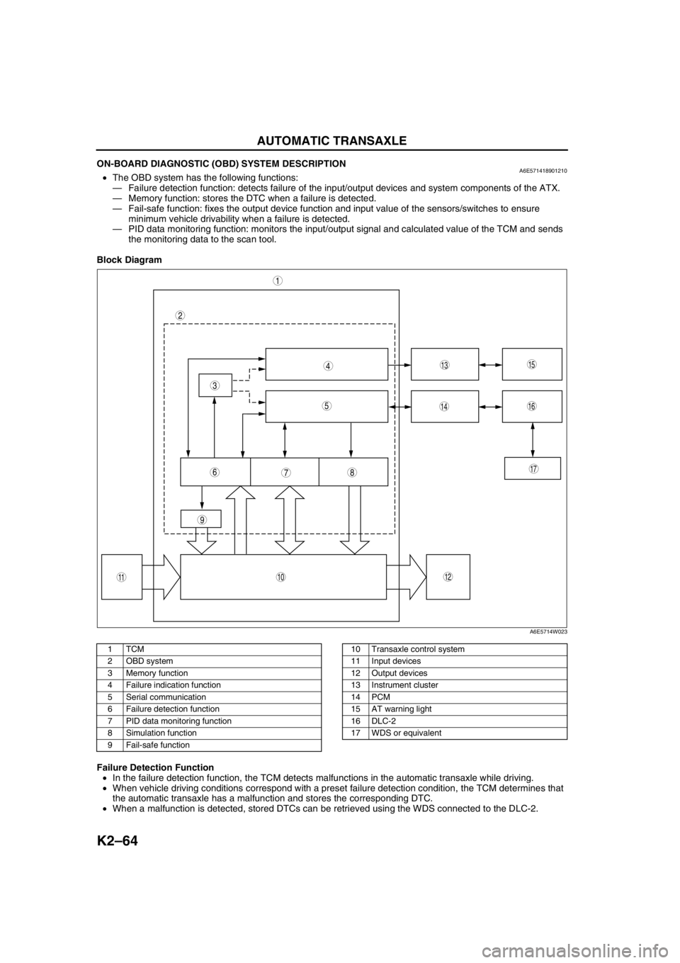
ON-BOARD DIAGNOSTIC (OBD) SYSTEM DESCRIPTIONA6E571418901210•The OBD system has the following functions:
—Failure detection function: detects failure of the input/output devices and system components of the ATX.
—Memory function: stores the DTC when a failure is detected.
—Fail-safe function: fixes the output device function and input value of the sensors/switches to ensure
minimum vehicle drivability when a failure is detected.
—PID data monitoring function: monitors the input/output signal and calculated value of the TCM and sends
the monitoring data to the scan tool.
Block Diagram
.
Failure Detection Function
•In the failure detection function, the TCM detects malfunctions in the automatic transaxle while driving.
•When vehicle driving conditions correspond with a preset failure detection condition, the TCM determines that
the automatic transaxle has a malfunction and stores the corresponding DTC.
•When a malfunction is detected, stored DTCs can be retrieved using the WDS connected to the DLC-2.
9
87
5
4
3
1
2
10
17
15
1614
13
1112
6
A6E5714W023
1TCM
2 OBD system
3 Memory function
4 Failure indication function
5 Serial communication
6 Failure detection function
7 PID data monitoring function
8 Simulation function
9 Fail-safe function10 Transaxle control system
11 Input devices
12 Output devices
13 Instrument cluster
14 PCM
15 AT warning light
16 DLC-2
17 WDS or equivalent
Page 751 of 909

P–18
DYNAMIC STABILITY CONTROL
K
HRR wheel-speedRR wheel-
speed sensorVehicle is stopped 0 (AC)
•Inspect related harness
•Inspect wheel-speed
sensor •Inspect using the wave profile.
(See P–19 Inspection Using An
Oscilloscope (Reference))
M
IRF wheel-speedRF wheel-
speed sensorVehicle is stopped 0 (AC)
•Inspect related harness
•Inspect wheel-speed
sensor •Inspect using the wave profile.
(See P–19 Inspection Using An
Oscilloscope (Reference))
Q
NLR wheel-speedLR wheel-speed
sensorVehicle is stopped 0 (AC)
•Inspect related harness
•Inspect wheel-speed
sensor •Inspect using the wave profile.
(See P–19 Inspection Using An
Oscilloscope (Reference))
G Battery (IG) Ignition switch Ignition switch ON B+•Inspect related harness
•Inspect ignition switch
L Brake switch Brake switchWhen brake pedal is
depressed10—14•Inspect related harness
•Inspect brake switch
OLateral-G
(lateral-G signal)Combine
sensorVehicle is stopped 2.2—2.8
•Inspect related harness
•Inspect combine sensor Left corneringFluctuation
between
2.5—4.0 V
Right corneringFluctuation
between
1.0—2.5 V
PCombine sensor
power outputCombine
sensorIgnition switch ON 4.75—5.25•Inspect related harness
•Inspect combine sensor
RSteering angle
(ground)Steering angle
sensor—Below 1.0•Inspect related harness
•Inspect steering angle
sensor
S Combine sensorCombine
sensor—3.5—5.0•Inspect related harness
•Inspect combine sensor
TYaw rate
(yaw rate signal)Combine
sensorVehicle is stopped 2.2—2.8
•Inspect related harness
•Inspect yaw rate sensor Right corneringFluctuation
between
2.5—4.62 V
Left corneringFluctuation
between
2.5—0.33 V
USteering angle
(neutral signal)Steering angle
sensorSteering position:
center position 25°—29°Below 1.0•Inspect related harness
•Inspect steering angle
sensor
Except above condition Approx. 4
VForward-G
(forward-G signal)Combine
sensorVehicle is stopped 2.2—2.8
•Inspect related harness
•Inspect combine sensor AccelerationFluctuation
between
2.5—4.0 V
Deceleration Fluctuation
between
1.0—2.5 V
WSteering angle
(steering angle
signal 2)Steering angle
sensor•Inspect using the wave profile.
(See P–19 Inspection Using An
Oscilloscope (Reference))•Inspect related harness
•Inspect steering angle
sensor
XSteering angle
(steering angle
signal 1)Steering angle
sensor•Inspect using the wave profile.
(See P–19 Inspection Using An
Oscilloscope (Reference))•Inspect related harness
•Inspect steering angle
sensor
YCombine sensor
(ground)Combine
sensor—Below 1.0•Inspect related harness
•Inspect combine sensor
AA DSC OFF switchDSC OFF
switchWhen switch is pressed Below 1.0
•Inspect related harness
•Inspect DSC OFF switch
When switch is not pressed B+
AB OBDKLN terminal of
DLC-2It cannot be determined with terminal
voltage whether the condition is good or bad
because advanced function diagnostic
output is performed with serial
communication. Inspect with service codes.•Inspect related harness
•Inspect DSC HU/CM Terminal Signal Connected to Test condition Voltage (V) Action