2002 MAZDA 6 obd
[x] Cancel search: obdPage 2 of 909

VEHICLE IDENTIFICATION NUMBERS (VIN)
U.K. specs.
JMZ GG12R20# 100001—
JMZ GG12T20# 100001—
JMZ GG14R20# 100001—
JMZ GG14T20# 100001—
JMZ GY19320# 100001—
JMZ GY19820# 100001—
JMZ GY19F20# 100001—
JMZ GY19F50# 100001—
JMZ GY19R20# 100001—
JMZ GY19T20# 100001—
JMZ GY89370# 100001—
European (L.H.D.) specs.
JMZ GG12R2✻# 100001—
JMZ GG12T2✻# 100001—
JMZ GG14R2✻# 100001—
JMZ GG14T2✻# 100001—JMZ GY1932✻# 100001—
JMZ GY1982✻# 100001—
JMZ GY19F2✻# 100001—
JMZ GY19F5✻# 100001—
JMZ GY19R2✻# 100001—
JMZ GY19T2✻# 100001—
JMZ GY8937✻# 100001—
GCC specs.
JM7 GG32F✻✻# 100001—
JM7 GG42F✻✻# 100001—
JM7 GG34F✻✻# 100001—
JM7 GG44F✻✻# 100001—
JM7 GY49F✻✻# 100001—
JM7 GY39F✻✻# 100001—
JM7 GY49F✻0# 100001—
JM7 GY39F✻0# 100001—
RELATED MATERIALS
Mazda6 Training Manual
(European (L.H.D. U.K.), GCC specs.) . . . . . . . . . . . . 3359–1*–02C
Mazda6 Workshop Manual
(European (L.H.D. U.K.), GCC specs.) . . . . . . . . . . . . 1730–1*–02C
Engine Workshop Manual L8, LF, L3 . . . . . . . . . . . . . . 1731–1*–02C
Engine Workshop Manual MZR–CD (RF Turbo) . . . . . 1744–1E–02D
Manual Transaxle Workshop Manual G35M–R . . . . . . 1732–1*–02C
Manual Transaxle Workshop Manual A65M–R . . . . . . 1739–1E–02D
Automatic Transaxle Workshop Manual FN4A–EL . . . 1623–10–98E
Automatic Transaxle Workshop Manual
Supplement FN4A–EL . . . . . . . . . . . . . . . . . . . . . . . . . 1746–1*–02C
Automatic Transaxle Workshop Manual JA5A–EL . . . 1738–1E–02D
Automatic Transaxle Workshop Manual
Supplement JA5AX–EL . . . . . . . . . . . . . . . . . . . . . . . . 1765–1*–02H
Mazda6 Wiring Diagram
(European (L.H.D.), GCC specs.) . . . . . . . . . . . . . . . . 5558–1*–02G
Mazda6 Wiring Diagram
(U.K. specs.) . . . . . . . . . . . . . . . . . . . . . . . . . . . . . . . . . 5559–1*–02G
Mazda6 Bodyshop Manual
(European (L.H.D. U.K.), GCC specs.) . . . . . . . . . . . . 3360–1*–02C
Mazda6 Bodyshop Manual Supplement
(European (L.H.D. U.K.), GCC specs.) . . . . . . . . . . . . 3368–1*–02I
EOBD Training Manual
(European (L.H.D. U.K.), Australian specs.) . . . . . . . 3345–1*–00B
* : Indicates the printing location
E: Europe
0: Japan
Page 8 of 909

NEW STANDARDS
GI–5
GINEW STANDARDS TABLEA6E202800020201•The following is a comparison of the previous standard and the new standard.
NEW STANDARDS
New Standard Previous Standard
Remark
Abbrevi-
ationNameAbbrevi-
ationName
AP Accelerator Pedal—Accelerator Pedal
ACL Air Cleaner—Air Cleaner
A/C Air Conditioning—Air Conditioning
BARO Barometric Pressure—Atmospheric Pressure
B+ Battery Positive VoltageV
BBattery Voltage
—Brake Switch—Stoplight Switch
—Calibration Resistor—Corrected Resistance #6
CMP sensor Camshaft Position Sensor—Crank Angle Sensor
CAC Charge Air Cooler—Intercooler
CLS Closed Loop System—Feedback System
CTP Closed Throttle Position—Fully Closed
—Closed Throttle Position Switch—Idle Switch
CPP Clutch Pedal Position—Clutch Position
CIS Continuous Fuel Injection System EGI Electronic Gasoline Injection System
CS sensor Control Sleeve Sensor CSP sensor Control Sleeve Position Sensor #6
CKP sensor Crankshaft Position Sensor—Crank Angle Sensor 2
DLC Data Link Connector—Diagnosis Connector
DTM Diagnostic Test Mode—Test Mode #1
DTC Diagnostic Trouble Code—Service Code(s)
DI Distributor Ignition—Spark Ignition
DLI Distributorless Ignition—Direct Ignition
EI Electronic Ignition—Electronic Spark Ignition #2
ECT Engine Coolant Temperature—Water Thermo
EM Engine Modification—Engine Modification
—Engine Speed Input Signal—Engine RPM Signal
EVAP Evaporative Emission—Evaporative Emission
EGR Exhaust Gas Recirculation—Exhaust Gas Recirculation
FC Fan Control—Fan Control
FF Flexible Fuel—Flexible Fuel
4GR Fourth Gear—Overdrive
—Fuel Pump Relay—Circuit Opening Relay #3
FSO
solenoidFuel Shut Off Solenoid FCV Fuel Cut Valve #6
GEN Generator—Alternator
GND Ground—Ground/Earth
HO2S Heated Oxygen Sensor—Oxygen Sensor With heater
IAC Idle Air Control—Idle Speed Control
—IDM Relay—Spill Valve Relay #6
—Incorrect Gear Ratio——
—Injection Pump FIP Fuel Injection Pump #6
—Input/Turbine Speed Sensor—Pulse Generator
IAT Intake Air Temperature—Intake Air Thermo
KS Knock Sensor—Knock Sensor
MIL Malfunction Indicator Lamp—Malfunction Indicator Light
MAP Manifold Absolute Pressure—Intake Air Pressure
MAF sensor Mass Air Flow Sensor—Airflow Sensor
MFI Multiport Fuel Injection—Multiport Fuel Injection
OBD On Board Diagnostic—Diagnosis/Self Diagnosis
Page 89 of 909
![MAZDA 6 2002 Workshop Manual Suplement F1–1
F1
F1FUEL AND EMISSION CONTROL SYSTEM
[L8, LF, L3]
OUTLINE.............................................................. F1-2
OUTLINE OF CONSTRUCTION ....................... F1-2
FEATURES .....](/manual-img/28/57057/w960_57057-88.png "MAZDA 6 2002 Workshop Manual Suplement F1–1
F1
F1FUEL AND EMISSION CONTROL SYSTEM
[L8, LF, L3]
OUTLINE.............................................................. F1-2
OUTLINE OF CONSTRUCTION ....................... F1-2
FEATURES .....")
F1–1
F1
F1FUEL AND EMISSION CONTROL SYSTEM
[L8, LF, L3]
OUTLINE.............................................................. F1-2
OUTLINE OF CONSTRUCTION ....................... F1-2
FEATURES ........................................................ F1-2
SPECIFICATIONS ............................................. F1-2
CONTROL SYSTEM DIAGRAM (4WD)............. F1-3
CONTROL SYSTEM WIRING DIAGRAM
(4WD).............................................................. F1-4
FUEL SYSTEM..................................................... F1-9
OUTLINE ........................................................... F1-9
STRUCTURAL VIEW......................................... F1-9
SYSTEM DIAGRAM ........................................ F1-10
FUEL PUMP (TRANSFER).............................. F1-10
QUICK RELEASE CONNECTOR (FUEL TANK
SIDE, TRANSFER HOSE PART) ................. F1-12
EXHAUST SYSTEM........................................... F1-13
OUTLINE ......................................................... F1-13
STRUCTURAL VIEW....................................... F1-13
CONTROL SYSTEM........................................... F1-14
OUTLINE ......................................................... F1-14
STRUCTURAL VIEW (4WD) ........................... F1-16
BLOCK DIAGRAM ........................................... F1-17
CONTROL DEVICE AND CONTROL
RELATIONSHIP CHART .............................. F1-19
CONTROLLER AREA NETWORK (CAN) ....... F1-21
OUTLINE............................................................ F1-22
SUPPLEMENTAL SERVICE
INFORMATION ............................................. F1-22
ENGINE TUNE-UP............................................. F1-22
IDLE SPEED INSPECTION (4WD) ................. F1-22
FUEL SYSTEM................................................... F1-23
FUEL TANK REMOVAL/INSTALLATION ........ F1-23
FUEL PUMP UNIT
REMOVAL/INSTALLATION .......................... F1-26
FUEL HOSE (FUEL TANK SIDE,
TRANSFER HOSE PART)
REMOVAL/INSTALLATION .......................... F1-29
EXHAUST SYSTEM........................................... F1-30
EXHAUST SYSTEM
REMOVAL/INSTALLATION .......................... F1-30
CONTROL SYSTEM........................................... F1-33
PCM INSPECTION (4WD)............................... F1-33
ON-BOARD DIAGNOSTIC................................. F1-50
OUTLINE ......................................................... F1-50
CONTROL DEVICE AND MONITORING
SYSTEM RELATIONSHIP CHART .............. F1-50
DIAGNOSTIC TEST MODE (4WD) ................. F1-50
DTC (4WD) ...................................................... F1-52
OBD DRIVE MODE ......................................... F1-52
DTC TABLE ..................................................... F1-54
TROUBLESHOOTING........................................ F1-57ENGINE SYMPTOM
TROUBLESHOOTING .................................. F1-57
QUICK DIAGNOSTIC CHART ......................... F1-58
NO.14 POOR FUEL ECONOMY ..................... F1-62
NO.22 VIBRATION CONCERNS
(ENGINE) ...................................................... F1-64 FEATURES
SERVICE
Page 140 of 909

F1–52
ON-BOARD DIAGNOSTIC
End Of Sie
DTC (4WD)A6E397018881204•Detection logics and conditions are as shown below.
Controller Area Network (CAN)
PCM cannot receive any signals from TCM (U0101)
•PCM cannot receive any signals from TCM.
End Of Sie
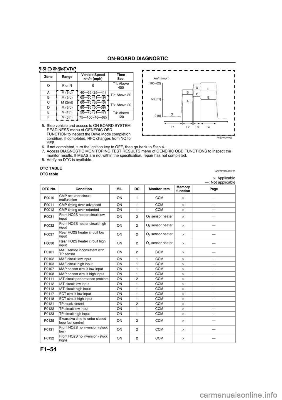
OBD DRIVE MODEA6E397018881205•Performing the Drive Mode inspects the OBD system for proper operation. The Drive Mode must be performed
to ensure that no additional DTCs are present.
•During Drive Mode, the following systems are inspected:
—Oxygen sensor (HO2S)
—Oxygen sensor heater
—Catalytic converter (TWC)
Caution
•While performing the Drive Mode, always operate the vehicle in a safe and lawful manner.
•When the WDS or equivalent is used to observe monitor system condition while driving, be sure to
have another technician with you, or record the data in the WDS or equivalent using the PID/DATA
MONITOR AND RECORD function and inspect later.
Note
•Vehicle speed and engine speed detected by the PCM may differ from that indicated by the speedometer
and tachometer. Use the WDS or equivalent to monitor vehicle speed.
•If the OBD system inspection is not completed during the Drive Mode, the following causes are
considered:
1. The OBD system detects the malfunction.
2. The Drive Mode procedure is not completed correctly.
•Disconnecting the battery will reset the memory. Do not disconnect the battery during and after Drive
Mode.
PCM Adaptive Memory Procedure Drive Mode
Note
•The PCM adaptive memory condition can be confirmed with RFCFLAG PID.
•If RFCFLAG PID is “Learnt”, PCM Adaptive Memory Procedure Drive Mode is not necessary, because
PCM already has adaptive memory.
•If RFCFLAG PID is “Not Learnt”, PCM Adaptive Memory Procedure Drive should be performed before
HO2S Heater, HO2S, and TWC Repair Verification Drive Mode.
1. Start the engine and warm it up completely.
2. Verify all accessory loads (A/C, headlights, blower fan, rear window defroster) are off.
U0101 PCM cannot receive any signals from TCM ON 1 Other×
U0121PCM cannot receive any signals from ABS, ABS/TCS
or DSC HU/CMON 1 Other×
U0155PCM cannot receive any signals from instrument
clusterON 1 Other× DTC No. Condition MIL DC Monitor itemMemory
function
Page 142 of 909
F1–54
ON-BOARD DIAGNOSTIC
For L3 engine ATX
5. Stop vehicle and access to ON BOARD SYSTEM
READINESS menu of GENERIC OBD
FUNCTION to inspect the Drive Mode completion
condition. If completed, RFC changes from NO to
YES.
6. If not completed, turn the ignition key to OFF, then go back to Step 4.
7. Access DIAGNOSTIC MONITORING TEST RESULTS menu of GENERIC OBD FUNCTIONS to inspect the
monitor results. If MEAS are not within the specification, repair has not completed.
8. Verify no DTC is available.
End Of Sie
DTC TABLEA6E397018881206DTC table
×: Applicable
—: Not applicable
Zone RangeVehicle Speed
km/h {mph}Time
Sec.
OP or N 0T1: Above
455
A M (3rd) 40—65 {25—41}
T2: Above 30
B M (3rd) 65—80 {41—49}
C M (2nd) 60—75 {38—46}
T3: Above 20
D M (3rd) 80—95 {50—59}
EM (4th)50—75 {31—47}
T4: Above
120
FM (5th)75—100 {46—62}km/h {mph}
100 {62}
50 {31}
0 {0}O
T1 T2 T3 T4A BD
C
E F
A6E3970W999
DTC No. Condition MIL DC Monitor itemMemory
functionPage
P0010CMP actuator circuit
malfunctionON 1 CCM×—
P0011 CMP timing over-advanced ON 1 CCM×—
P0012 CMP timing over-retarded ON 1 CCM×—
P0031Front HO2S heater circuit low
inputON 2O
2 sensor heater
×—
P0032Front HO2S heater circuit high
inputON 2O
2 sensor heater
×—
P0037Rear HO2S heater circuit low
inputON 2O
2 sensor heater
×—
P0038Rear HO2S heater circuit high
inputON 2O
2 sensor heater
×—
P0101MAF sensor inconsistent with
TP sensorON 2 CCM×—
P0102 MAF circuit low input ON 1 CCM×—
P0103 MAF circuit high input ON 1 CCM×—
P0107 MAP sensor circuit low input ON 1 CCM×—
P0108 MAP sensor circuit high input ON 1 CCM×—
P0111 IAT circuit performance problem ON 2 CCM×—
P0112 IAT circuit low input ON 1 CCM×—
P0113 IAT circuit high input ON 1 CCM×—
P0117 ECT circuit low input ON 1 CCM×—
P0118 ECT circuit high input ON 1 CCM×—
P0121 TP stuck closed ON 2 CCM×—
P0122 TP circuit low input ON 1 CCM×—
P0123 TP circuit high input ON 1 CCM×—
P0125Excessive time to enter closed
loop fuel controlON 2 CCM×—
P0131Front HO2S no inversion (stuck
low)ON 2 CCM×—
P0132Front HO2S no inversion (stuck
high)ON 2 CCM×—
Page 416 of 909
![MAZDA 6 2002 Workshop Manual Suplement K2–1
K2
K2AUTOMATIC TRANSAXLE [JA5AX-EL]
OUTLINE.............................................................. K2-3
FEATURES ........................................................ K2-3
SPECIFICATI](/manual-img/28/57057/w960_57057-415.png "MAZDA 6 2002 Workshop Manual Suplement K2–1
K2
K2AUTOMATIC TRANSAXLE [JA5AX-EL]
OUTLINE.............................................................. K2-3
FEATURES ........................................................ K2-3
SPECIFICATI")
K2–1
K2
K2AUTOMATIC TRANSAXLE [JA5AX-EL]
OUTLINE.............................................................. K2-3
FEATURES ........................................................ K2-3
SPECIFICATIONS ............................................. K2-3
AUTOMATIC TRANSAXLE.................................. K2-4
OUTLINE ........................................................... K2-4
CROSS-SECTIONAL VIEW .............................. K2-6
ELECTRONIC CONTROL SYSTEM
STRUCTURAL VIEW...................................... K2-8
AUTOMATIC TRANSAXLE CONTROL SYSTEM
WIRING DIAGRAM ....................................... K2-10
AUTOMATIC TRANSAXLE BLOCK
DIAGRAM ..................................................... K2-11
AUTOMATIC TRANSAXLE DEVICE
RELATIONSHIP CHART .............................. K2-13
POWERTRAIN DESCRIPTION ....................... K2-15
TORQUE CONVERTER DESCRIPTION......... K2-40
OIL PUMP DESCRIPTION .............................. K2-41
CENTRIFUGAL BALANCE CLUTCH
DESCRIPTION ............................................. K2-42
CONTROL VALVE BODY DESCRIPTION ...... K2-43
TRANSAXLE FLUID TEMPERATURE
(TFT) SENSOR DESCRIPTION ................... K2-45
INPUT/TURBINE SPEED SENSOR
DESCRIPTION ............................................. K2-45
INTERMEDIATE SENSOR DESCRIPTION..... K2-46
VEHICLE SPEEDOMETER SENSOR
DESCRIPTION ............................................. K2-46
SOLENOID VALVE DESCRIPTION ................ K2-47
CONTROLLER AREA NETWORK (CAN)
DESCRIPTION ............................................. K2-50
TRANSAXLE CONTROL MODULE
(TCM) DESCRIPTION .................................. K2-51
SHIFT CONTROL DESCRIPTION .................. K2-51
MANUAL MODE SHIFT CONTROL
DESCRIPTION ............................................. K2-52
LINE PRESSURE CONTROL DESCRIPTION K2-54
FEEDBACK CONTROL DESCRIPTION ......... K2-57
N-D SELECT CONTROL DESCRIPTION........ K2-59
TORQUE CONVERTER CLUTCH
(TCC) CONTROL DESCRIPTION ................ K2-59
SLOPE MODE CONTROL DESCRIPTION ..... K2-63
ON-BOARD DIAGNOSTIC (OBD)
SYSTEM DESCRIPTION.............................. K2-64
COOLING SYSTEM DESCRIPTION ............... K2-69
LOCATION INDEX............................................. K2-70
AUTOMATIC TRANSAXLE LOCATION
INDEX ........................................................... K2-70
AUTOMATIC TRANSAXLE................................ K2-72
MECHANICAL SYSTEM TEST ....................... K2-72
ROAD TEST .................................................... K2-75AUTOMATIC TRANSAXLE FLUID
(ATF) INSPECTION ...................................... K2-78
AUTOMATIC TRANSAXLE FLUID
(ATF) REPLACEMENT ................................. K2-80
TRANSAXLE RANGE (TR) SWITCH
INSPECTION ................................................ K2-80
TRANSAXLE RANGE (TR) SWITCH
REMOVAL/INSTALLATION .......................... K2-81
TRANSAXLE RANGE (TR) SWITCH
ADJUSTMENT .............................................. K2-83
TRANSAXLE FLUID TEMPERATURE
(TFT) SENSOR INSPECTION ...................... K2-84
TRANSAXLE FLUID TEMPERATURE
(TFT) SENSOR REMOVAL/INSTALLATION K2-85
INPUT/TURBINE SPEED SENSOR
INSPECTION ................................................ K2-85
INPUT/TURBINE SPEED SENSOR
REMOVAL/INSTALLATION .......................... K2-86
INTERMEDIATE SENSOR INSPECTION ....... K2-86
INTERMEDIATE SENSOR
REMOVAL/INSTALLATION .......................... K2-86
VEHICLE SPEEDOMETER SENSOR
(VSS) INSPECTION...................................... K2-87
VEHICLE SPEEDOMETER SENSOR
(VSS) REMOVAL/INSTALLATION ............... K2-87
SOLENOID VALVE INSPECTION ................... K2-88
SOLENOID VALVE
REMOVAL/INSTALLATION .......................... K2-90
TCM INSPECTION .......................................... K2-90
TCM REMOVAL/INSTALLATION .................... K2-96
AUTOMATIC TRANSAXLE AND
TRANSFER REMOVAL/INSTALLATION...... K2-99
OIL SEAL REMOVAL/INSTALLATION .......... K2-104
CONTROL VALVE BODY
REMOVAL/INSTALLATION ........................ K2-105
OIL COOLER FLUSHING .............................. K2-106
OIL COOLER REMOVAL/INSTALLATION .... K2-108
OIL COOLER DISASSEMBLY/ASSEMBLY .. K2-110
DRIVE PLATE REMOVAL/INSTALLATION... K2-112
TRANSFER....................................................... K2-114
TRANSFER OIL INSPECTION ...................... K2-114
TRANSFER OIL REPLACEMENT ................. K2-114
TRANSFER REMOVAL/INSTALLATION....... K2-115
BREATHER PLUG
REMOVAL/INSTALLATION ........................ K2-116
AUTOMATIC TRANSAXLE SHIFT
MECHANISM................................................. K2-117
SELECTOR LEVER INSPECTION ................ K2-117
SELECTOR LEVER COMPONENT
INSPECTION .............................................. K2-117
SELECTOR CABLE ADJUSTMENT .............. K2-118
SELECTOR LEVER
REMOVAL/INSTALLATION ........................ K2-119
SELECTOR LEVER
DISASSEMBLY/ASSEMBLY ...................... K2-122
ON-BOARD DIAGNOSTIC............................... K2-123
FOREWORD .................................................. K2-123 FEATURES
SERVICE
Page 427 of 909

K2–12
AUTOMATIC TRANSAXLE
Electronic Control Item and Control
Component Description (Electronic Control)
Control item Contents
Shift control•Detects engine load condition and vehicle speed. Shifts to the best gear
position according to the programmed automatic shift diagram.
Line pressure control•Generates line pressure matching the engine load condition and driving
conditions. Optimizes line pressure for each shift. When the ATF
temperature is low, automatically optimizes line pressure for quick clutch
engagement.
Revers inhibition control•When the shift lever is shifted to R position while the vehicle is running
forward at approx. 30 km/h{19 mph} or more, the TCM turns the neutral
shift solenoid valve on and drains the low and reverse brake hydraulic
pressure. Due to this, the transaxle shifts to neutral.
Shift transient control•Adjusts transient hydraulic pressure according to engine load and
vehicle driving conditions when shifting using the pressure control
solenoid, 2-4 brake solenoid valve, the high clutch solenoid valve, and
each accumulator control valve.
•Temporarily lowers engine torque during shift (up and down) to improve
shift feel
•The lock timing for the reduction brake band is controlled by the control
of the reduction timing solenoid valve ON/OFF timing.
•The lock timing for the clutch brake is controlled by the control of shift
solenoid A, B, and C ON/OFF timing.
Feedback control•Corrects clutch engagement pressure and timing on drain side to
compensate for changes in engine performance and changes in
transaxle
TCC control•Controls TCC according to the programmed TCC points
N-D select control•When a driving range is selected from P/N, the fuel injection amount is
controlled to prevent fluctuation in engine speed.
Slope mode control•Changes the shift point to prevent frequent shifting up/down when
climbing hills
OBD system•Detects and/or memorizes failure of input/output part and transaxle
condition
Part name Function
Input system TR switch•Detects selector lever ranges/positions
Input/turbine speed sensor•Detects reverse clutch drum revolution speed
Intermediate sensor•Detects output gear revolution speed
Vehicle speedometer sensor•Detects parking gear revolution speed
TFT sensor•Detects the ATF temperature
Brake switch•Detects the brake pedal depressed
Cruise control module (in cruise actuator)•When the cruise control is in use, the signal detects when the
difference between the target speed and actual speed
exceeds specification
M range switch•Detects selector lever shifted M range
Up switch•Detects up shift in M range
Down switch•Detects down shift in M range
CAN signal Throttle position signal•Input throttle opening angle from PCM
Engine torque signal
(without torque down)•Input engine torque from PCM
Engine torque signal (with
torque down)•Input engine torque from PCM
Engine torque signal (loss
torque)•Input engine loss torque from PCM
Torque reduced signal•Detects signals indicating torque down availability
Engine coolant
temperature signal•Input engine coolant temperature from PCM
Engine speed signal•Input engine speed from PCM
Battery OFF signal•Detect negative battery cable disconnected
4 wheel speed signal•Input wheel speed from ABS HU/CM or DSC HU/CM
Page 428 of 909

AUTOMATIC TRANSAXLE
K2–13
K2
End Of SieAUTOMATIC TRANSAXLE DEVICE RELATIONSHIP CHARTA6E571401030206
Output system ON/OFF
typeShift solenoid A•Switches ON and OFF based on electric signals from the
TCM, changes hydraulic circuit to control shifting
Shift solenoid B•Switches ON and OFF based on electric signals from the
TCM, changes hydraulic circuit to control shifting
Shift solenoid C•Switches ON and OFF based on electric signals from the
TCM, changes hydraulic circuit to control shifting
Reduction timing solenoid
valve•Switches ON and OFF based on electric signals from the
TCM, changes hydraulic circuit to control shifting
Neutral shift solenoid valve•Switches ON and OFF based on electric signals from the
TCM, changes hydraulic circuit to control shifting
Duty type
Pressure control solenoid•Switches ON and OFF based on electric signal (duty signals)
from the TCM adjusts line pressure to match driving
conditions
2-4 brake solenoid valve•Switches ON and OFF based on electric signal (duty signals)
from the TCM adjusts line pressure to match driving
conditions
High clutch solenoid valve•Switch ON and OFF based on electric signal (duty signals)
from the TCM adjusts line pressure to match driving
conditions
TCC solenoid valve•Switch ON and OFF based on electric signal (duty signals)
from the TCM to control TCC
CAN signal Reduce torque signal•Sends signals to the PCM during shifting
Range signal•Output transaxle load condition to PCM
Turbine speed signal•Output turbine speed to PCM
ATF temperature signal•Output ATF high temperature signal to PCM
TCC signal•Output TCC signal to PCM
Racing select signal•Requests fuel cut when selector lever is shifted during racing
MIL indicate request signal•Requests MIL illumination when failure is detected by
diagnosis function
AT warning light request
signal•Requests AT warning light indication when failure is detected
by diagnosis function for ATX Part name Function
ComponentControl item
Shift
controlLine
pressure
controlReverse
inhibition
controlShift
transient
controlFeedbac
k controlTCC
controlN-D
select
controlSlope
mode
controlOBD
system
Input
TR switch XXXXXXX X
Input/turbine
speed sensorX XXXXXX
Intermediate
sensorXXX X
Vehicle
speedometer
sensorXXXXXXXXX
TFT sensor XX XXXX X
Brake switch X X X
Cruise control
module (4GR
inhibit signal)XX
M range switch X X
Up switch X X
Down switch X X